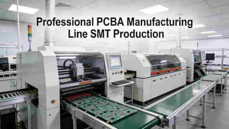
|

How to Solder on PCB: Essential Techniques and Best Practices for Reliable Assembly

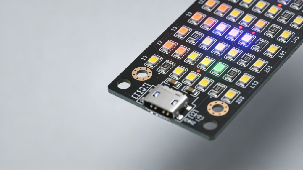
PCB soldering basics showing solder joint structure and component connection

PCB soldering is the foundation of reliable electronics assembly. This professional guide covers proven methods for how to solder on PCB, including hand soldering, wave soldering, reflow soldering, and selective soldering, with industrial best practices to eliminate defects and ensure long-term performance for industrial, automotive, and aerospace applications.

What is PCB Soldering? A Foundation for Reliability

PCB soldering is the metallurgical process of bonding electronic components to a printed circuit board using a molten solder alloy that forms a permanent mechanical and electrical connection. It transforms a bare PCB into a functional circuit assembly.

Modern PCB assembly primarily uses lead-free solder alloys (such as SAC – Tin-Silver-Copper) to comply with global RoHS environmental standards while maintaining high joint reliability.
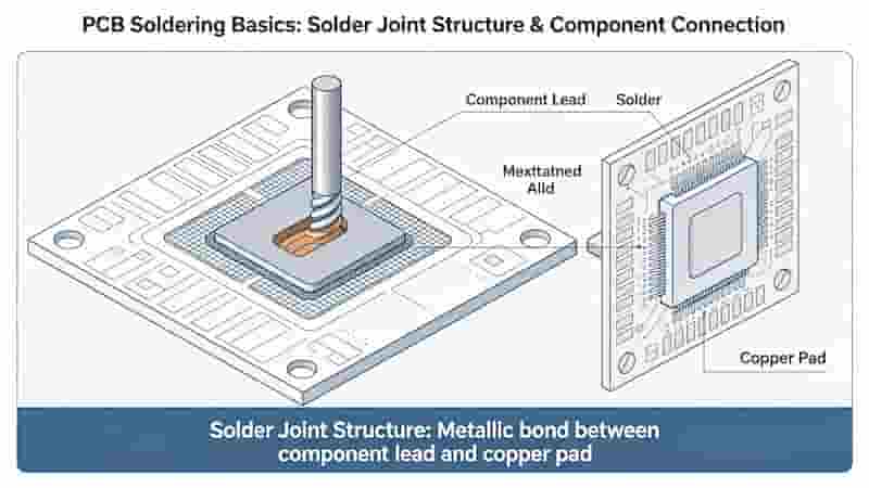
PCB soldering basics showing solder joint structure and component connection

Key Techniques on How to Solder on PCB

1. Hand Soldering

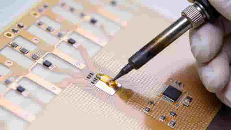
Hand soldering is ideal for prototyping, repairs, and low-volume PCB assembly. It uses a temperature-controlled soldering iron to form precise joints manually.

  • Clean surfaces and apply flux for better wetting
  • Heat the pad and component lead evenly
  • Apply solder to form a shiny, concave fillet
  • Avoid overheating to prevent pad damage
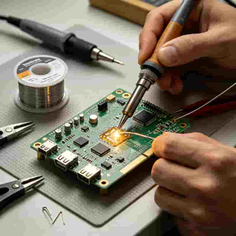
Hand soldering on PCB showing proper technique and tools

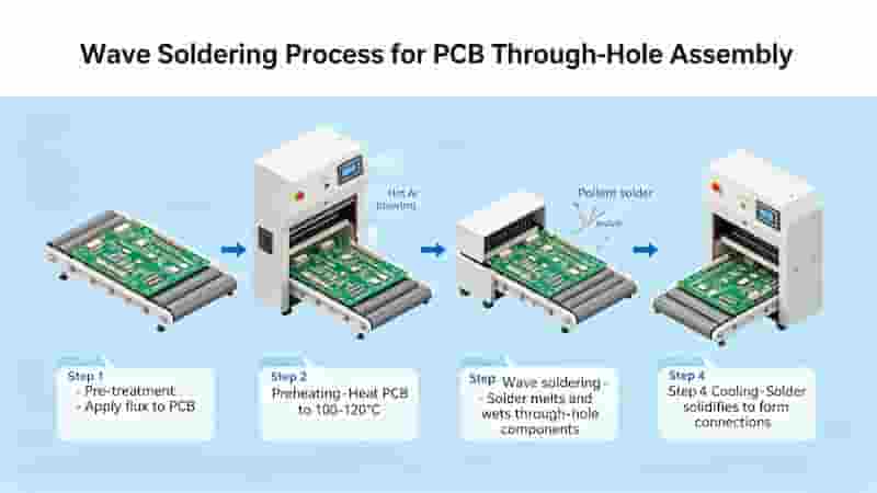
2. Wave Soldering

Wave soldering is an automated process for through-hole components, where the PCB passes over a molten solder wave to create consistent joints.

  • Flux application prevents oxidation
  • Preheating avoids thermal shock
  • Solder wave forms reliable through-hole connections
  • Controlled cooling stabilizes joints
Wave soldering process for PCB through-hole assembly

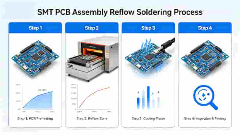
3. Reflow Soldering

Reflow soldering is the industry standard for SMT PCB assembly, using solder paste and thermal profiling to attach surface-mount components.

  • Solder paste printing via precision stencils
  • Component placement by pick-and-place machines
  • Controlled reflow oven thermal profiling
  • Cooling to form stable SMT joints
Reflow soldering process for SMT PCB assembly

4. Selective Soldering

Selective soldering targets specific areas on mixed-technology PCBs, protecting sensitive SMT components while soldering through-hole parts.

  • Programmable precision for complex boards
  • Minimizes thermal stress to components
  • Ideal for connectors and high-profile parts
Soldering MethodBest ForAdvantages
Hand SolderingPrototypes, RepairsLow cost, flexible
Wave SolderingThrough-hole PCBsHigh throughput
Reflow SolderingSMT / High-density boardsPrecise, scalable
Selective SolderingMixed-technology PCBsTargeted, low stress

Critical Considerations for SMT PCB Soldering

High-quality how to solder on PCB for SMT requires strict control over these factors:

  • Solder pad design (NSMD preferred for alignment)
  • Solder paste type, particle size, and flux chemistry
  • Precise thermal profiling (1-3°C/sec ramp rate)
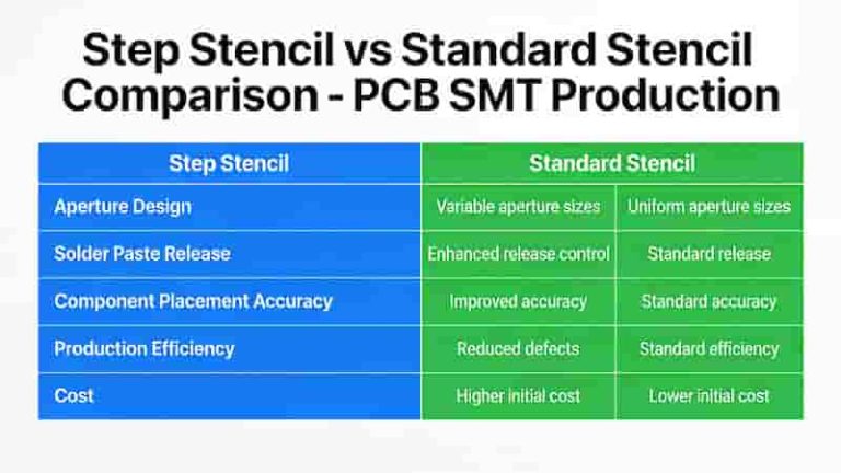
  • Stencil thickness and aperture optimization
  • ESD protection for sensitive components

PCB Soldering Rework: Step-by-Step Industrial Guide

  1. Preheat PCB to remove moisture and reduce stress
  2. Use hot air to melt existing solder joints
  3. Clean pads with desoldering braid
  4. Apply fresh solder paste and reflow
  5. Inspect with magnification or AOI

Common Mistakes to Avoid in PCB Soldering

  • Overheating: Causes lifted pads and component damage
  • Insufficient Flux: Leads to cold joints and poor wetting
  • Bad Thermal Profiling: Creates tombstones, bridges, and voids
  • Poor Cleaning: Flux residue causes corrosion and leakage

Conclusion

Mastering how to solder on PCB ensures robust, reliable, and long-lasting electronic assemblies. From manual hand soldering to automated SMT processes, following industrial best practices eliminates defects and improves production yield.

Need Professional PCB Assembly & Soldering Services?

We provide high-quality PCB soldering, SMT assembly, and turnkey manufacturing for industrial, automotive, and aerospace applications. Contact us for a free quote or technical support today.

Inquire Now & Get Your Quote
Multilayer HDI Rigid-Flex PCB Types

Rigid-Flex PCB Manufacturing & Prototype Services

We are a leading China-based Rigid-Flex PCB manufacturer specializing in 1–12 layer rigid-flex PCB prototype, small-to-large volume fabrication, and full assembly with fast turnaround, free DFM check, and ISO/UL/RoHS certification. Benefits of Rigid-Flex PCB Rigid-Flex PCB integrates the stability of rigid boards with the flexibility of flex circuits, delivering superior performance for compact, high‑reliability electronic…
PCB basic structure diagram showing trace pad silkscreen component

PCB Terminology Glossary – Over 150 Essential PCB Terms for Engineers & Global Buyers

This professional PCB glossary provides clear, industry-standard definitions for over 150 key terms used in PCB design, manufacturing, assembly, and quality control. Ideal for engineers, procurement teams, and global buyers, this resource helps streamline communication, avoid misunderstandings, and ensure accurate project execution. We continuously update this list to cover the latest technologies and standards in…
PTH Component Mounting in PCB

What Is the Difference Between PTH and Via in PCBs?

Understanding the key differences between PTH and via is essential for optimizing PCB design and manufacturing. This article defines PTH and via, compares dimensions, functions, locations and finishing requirements. Typical applications and design considerations are also discussed to help engineers and buyers make informed decisions. Defining PTH and Vias in PCBs PTHs (Plated Through Holes)…
Tented vias application in HDI SMT industrial PCB

What Are Tented Vias? A Complete PCB Design Guide

Learn what tented vias are, how they work, key benefits, IPC standards, design rules, and best applications for high‑performance PCB manufacturing and assembly. What Is a Tented Via in PCBs? A tented via is a plated through‑hole (PTH), blind via, or buried via fully or partially covered with solder mask on one or both sides…
THT PCB Assembly with DIP components through hole technology

Demystifying THT PCB Assembly: A Comprehensive Professional Guide

In the ever-evolving world of electronics manufacturing, THT PCB assembly remains a crucial process for many applications. This comprehensive guide delves into the intricacies of through‑hole assembly, exploring processes, techniques, advantages, and future trends. Discover the unique strengths of THT and how it complements surface mount technology in modern product designs. What Is THT PCB…
SMT PCB Assembly Line High Precision

Turnkey PCB Assembly Services | Full & Partial Solutions

We provide end-to-end turnkey PCB assembly supporting full and partial models, with SMT assembly, THT, BGA/QFN, rigorous testing, and global logistics for industrial buyers, engineers, and importers. What Is Turnkey PCB Assembly Turnkey PCB assembly is a one-stop manufacturing solution covering PCB fabrication, component sourcing, assembly, testing, and delivery. We manage the full supply chain…

FAQs About PCB Soldering & Four Core Soldering Technologies

A: It is a metallurgical bonding process using molten solder to fix components onto PCB and form stable mechanical & electrical connections; most modern products adopt lead-free SAC solder to meet RoHS rules.

A: Hand soldering for prototype & repair; Wave soldering for mass through-hole assembly; Reflow soldering for SMT high-density boards; Selective soldering for mixed SMT+through-hole PCBs.

A: Solder paste stencil printing → component pick & place → staged heating in reflow oven → controlled cooling to finish SMT joints.

A: Pad design, solder paste & flux type, stencil aperture, reflow thermal ramp rate and complete ESD protection management.

A: Preheat PCB → hot air melt old solder → clean pads with desoldering braid → apply new solder paste → reflow and final AOI inspection.

A: Overheating leads to lifted pads; insufficient flux brings cold joints; wrong thermal profile causes tombstoning, bridging and voids; residual flux triggers later corrosion leakage.

A: It only heats target through-hole positions, effectively avoiding thermal damage to surrounding sensitive SMT components on mixed-technology PCBs.

A: Flux removes surface oxidation of pads and leads, improves solder wetting performance and prevents incomplete fusion and poor solder joints.

Similar Posts