Learn industrial-grade methods to safely and accurately detect PCB short circuits using visual inspection, multimeters, thermal imaging, and X-ray, compliant with IPC standards for electronics manufacturing and repair.
Understanding PCB Short Circuits
The distinctive burnt smell from faulty electronics often signals a PCB short circuit. This occurs when current flows along an unintended path, causing overheating, component damage, or complete board failure. Identifying and resolving PCB short circuits is critical to maintaining product reliability and reducing costly rework.
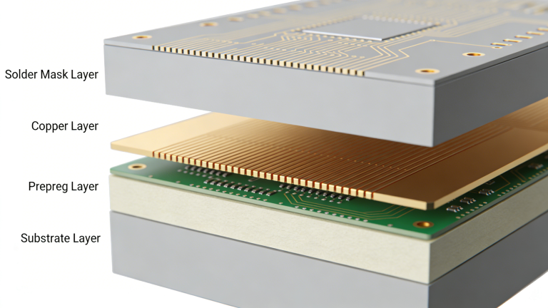
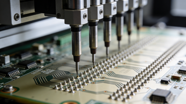
Quality control for printed circuit boards combines testing and inspection methods, including visual inspection, multimeter testing, destructive testing, and advanced non-destructive analysis. These processes ensure your PCB assemblies meet international quality standards before deployment.
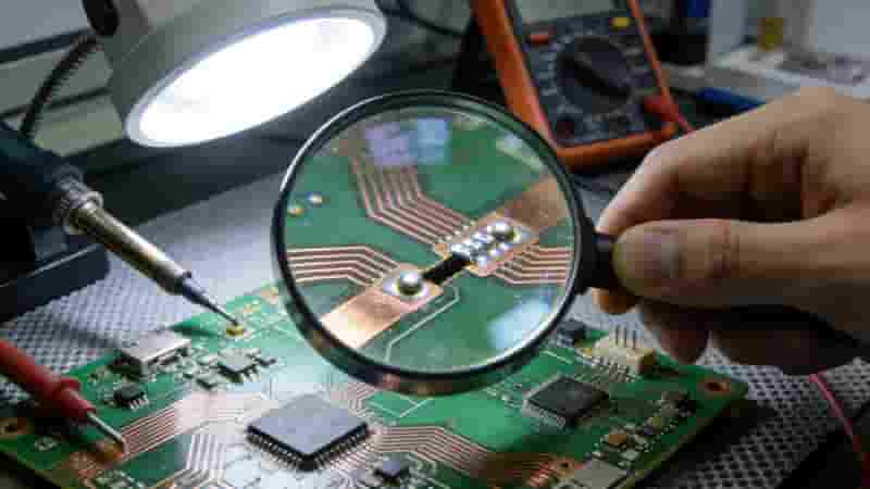
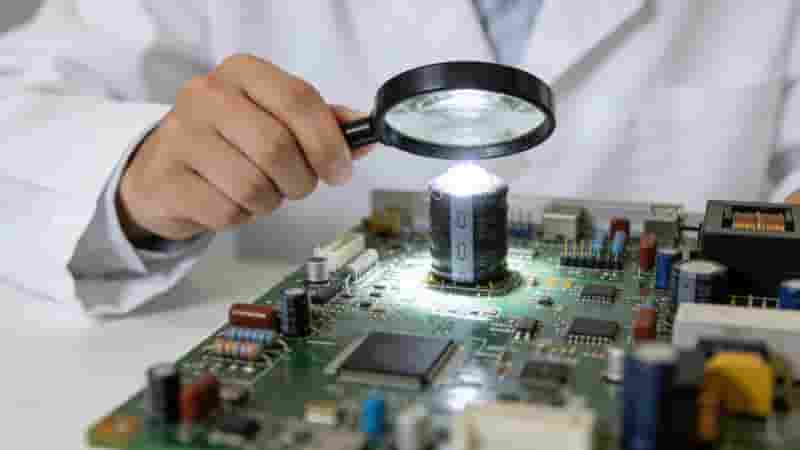
Step 1: Visual Inspection
Begin with visual inspection using magnification tools such as magnifying glasses or low-power microscopes. Check for solder bridges, tin whiskers between joints, cracked traces, excess solder blobs, and poorly plated vias that may create layer-to-layer PCB short circuits.
Visible burn marks indicate severe damage. For hidden issues in inner layers, use infrared imaging to detect abnormal hotspots caused by PCB short circuits.
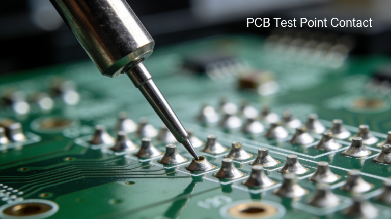
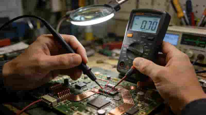
Step 2: Multimeter Testing
When visual inspection is insufficient, use a multimeter to measure resistance across critical points. Set the device to continuity or low-resistance mode to identify PCB short circuits between traces, pads, or power-ground planes.
Place one probe on a ground connection and test other conductors. High resistance readings are normal; low readings without inductive components suggest a PCB short circuit. Verify resistance between IC pins, connector pins, and related pads to isolate faults.
Step 3: Component Checking
Faulty or improperly installed components often cause PCB short circuits. Inspect for bulging, burnt, or damaged parts. Physical deformities on the PCB surface can reveal which components have failed and created short paths.
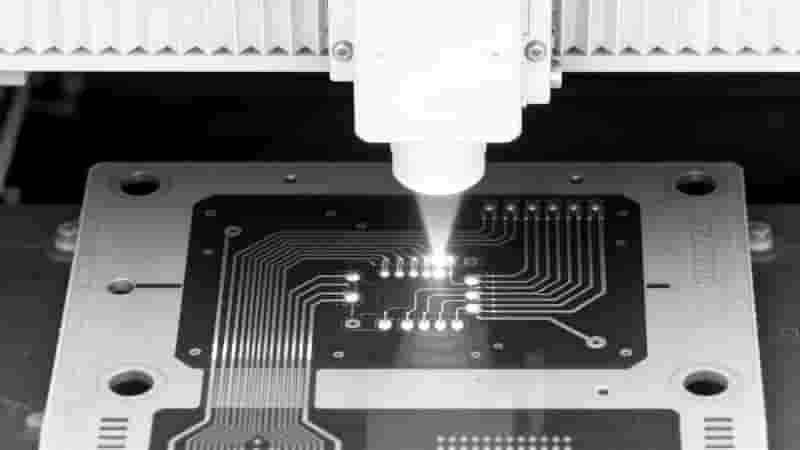
Step 4: Advanced and Destructive Testing
For unresolved PCB short circuits, use X-ray imaging to examine inner layers non-destructively. If X-ray is unavailable, remove components and repeat multimeter tests to isolate whether the short originates from the board or faulty parts.
This process confirms if internal pad bridging or substrate defects are causing the PCB short circuit, supporting accurate root-cause analysis.
PCB Short Testing Method Comparison
| Method | Best For | Accuracy | Cost |
|---|---|---|---|
| Visual Inspection | Obvious solder defects | Low | Very Low |
| Multimeter Test | General PCB short detection | Medium | Low |
| Component Check | Part-related shorts | Medium | Low |
| Thermal Imaging | Hidden and power shorts | High | Medium |
| X-Ray Inspection | Inner-layer PCB short circuits | Very High | High |
Summary
Detecting PCB short circuits requires a systematic approach: visual inspection, multimeter testing, component verification, and advanced analysis. These steps minimize downtime and prevent costly failures. Partnering with a qualified manufacturer ensures rigorous testing before delivery, eliminating the need for extensive in-house troubleshooting.
Contact Us for Reliable PCB Solutions
We specialize in high-quality PCB manufacturing and assembly with strict short-circuit prevention and full IPC compliance. Every board undergoes comprehensive testing to ensure reliability and performance.
We offer competitive pricing, fast lead times, and professional technical support for global clients. Send your Gerber files, BOM, and project details for a free quotation and DFM review today.
Email: chen2351392011@gmail.com | WhatsApp: +15946990203