This professional guide covers HDI PCB layout practices, stack-up, microvias, routing rules, DFM, impedance control and IPC standards to help engineers and procurement teams build reliable, mass-producible HDI PCB for high-speed, miniaturized electronics.
What Is HDI PCB Layout
HDI PCB (High-Density Interconnect) layout refers to design methods used when trace widths drop below 8 mils (0.2 mm). It allows higher component density, smaller board size, and better electrical performance for modern electronics.
Key Features of HDI PCB
A typical HDI PCB includes these critical characteristics to support high-density designs:
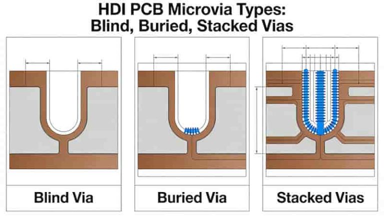
- Microvias (laser-drilled blind & buried vias)
- Fine traces: 3–5 mils for high wiring density
- Thin dielectric layers for impedance control
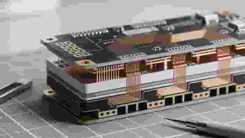
- High layer counts up to 20+ layers for complex systems
- Low signal loss design for high-speed circuits
Trace & Via Design for HDI PCB
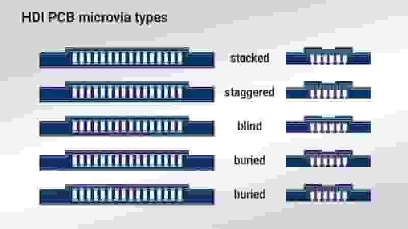
Vias are the most critical part of HDI PCB layout. Through-hole vias are rarely used; microvias with aspect ratio ≤ 1:1 are preferred for reliability.
- Microvia diameter: 2–4 mils (50–100 μm)
- Stacked & staggered vias for layer transitions
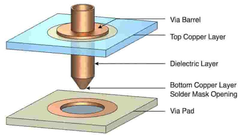
- VIPPO (Via-in-Pad Plated Over) for fine-pitch BGAs
- Follow IPC-2221A for aspect ratio limits
Basic HDI Design Guidelines
These universal rules apply to all HDI PCB layout projects to ensure manufacturability and performance:
- Confirm your manufacturer’s capabilities before design
- Maintain consistent trace spacing and impedance
- Avoid unnecessary ELIC or complex via structures
- Use minimal layer count to reduce cost
- Prioritize signal integrity for high-speed designs
BGA Fanout & Routing in HDI PCB Layout
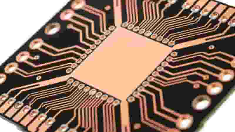
Fine-pitch BGAs require specialized fanout strategies in HDI PCB design:
- 0.8 mm pitch: Dogbone fanout with microvias
- 0.5–0.75 mm pitch: VIPPO (via-in-pad)
- Route between pads only if traces ≤ 4 mils are supported
DFM Rules for HDI PCB
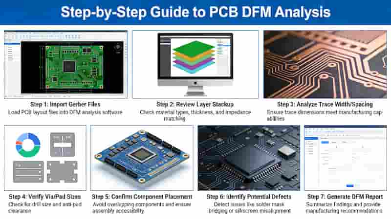
DFM (Design for Manufacturing) ensures your HDI PCB layout can be produced with high yield and stable quality.
- Match trace/space to factory capabilities
- Use valid solder mask clearances
- Include test points for electrical testing
- Follow IPC-6012 for quality classification
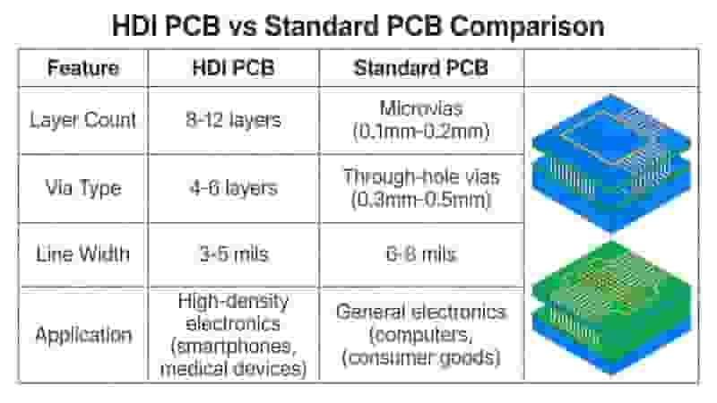
HDI PCB vs Standard PCB
| Item | HDI PCB | Standard PCB |
|---|---|---|
| Trace Width | 3–5 mils | ≥6 mils |
| Via Type | Microvia, Blind, Buried | Through-hole |
| Density | Ultra High | Standard |
| Application | 5G, AI, Automotive, Mobile | Industrial, Power, Control |
Conclusion
Following professional HDI PCB layout and design guidelines is essential for creating reliable, cost-effective, and mass-producible HDI boards. Correct via design, impedance control, and DFM compliance directly improve yield and performance.
Get Your HDI PCB Solution
We provide professional HDI PCB manufacturing, assembly and design support for global buyers. Request a free quote now.
Request HDI Quote
Copper Core PCB vs. Metal Core PCB: Key Differences & Advantages
Rigid-Flex PCB Stackup: Design and Manufacturing Guide

Essential Materials for Surface Mount Technology: A Comprehensive Guide
Aluminum PCB vs FR4 PCB: Full Technical Comparison for Industrial & Export Buyers
Low-Cost PCB Assembly Service | Reliable Provider & Cheap PCB Solutions