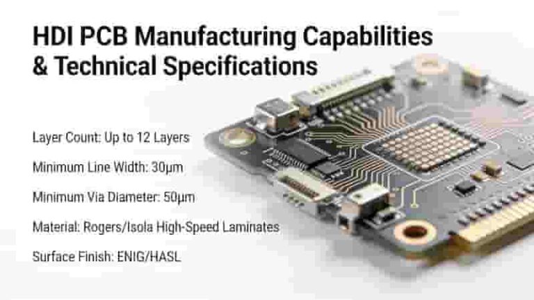
Microvias are core interconnect structures that enable extreme miniaturization in PCBs. This guide covers definitions, types, fabrication, reliability, applications, and design best practices for global industrial buyers, engineers, and procurement teams.
What Are PCB Microvias?
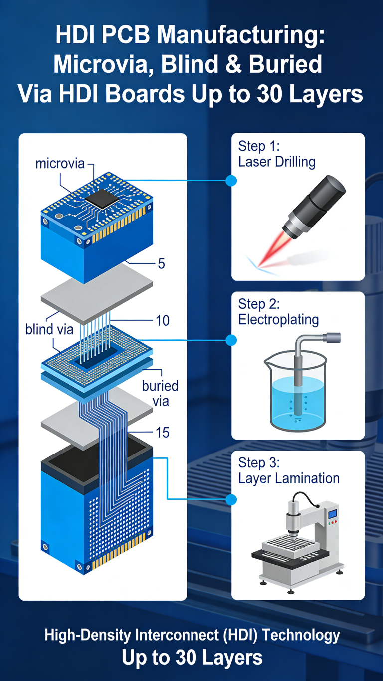
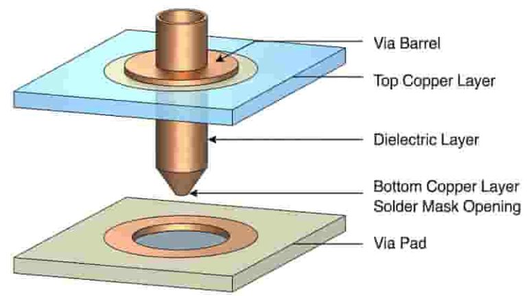
As printed circuit boards are designed to pack more components into increasingly compact spaces, microvias play a crucial role in enabling further miniaturization. A microvia is a small via used to interconnect layers in high density PCBs.
Measuring typically between 0.005–0.015 inches (0.13–0.38mm) or less in diameter, microvias reduce PCB thickness and layer count while maintaining electrical performance. This allows more functionality to be integrated into shrinking electronics hardware.
Traditional through-hole vias occupy substantial space and limit routing channels, becoming obstacles to miniaturization. Laser‑drilled or photo‑imageable microvias minimize routing disruptions and optimize vertical interconnects.
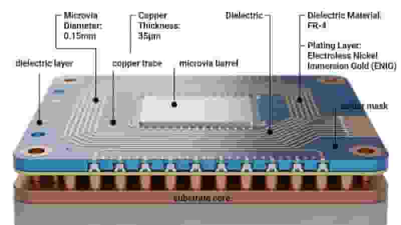
Types of Microvias
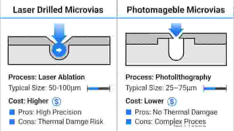
There are two primary technologies for producing microvias in PCBs: laser drilling and photoimaging. Each offers distinct process advantages.
Laser-Drilled Microvias
Laser drilling uses YAG, CO₂, or excimer lasers to selectively ablate materials. It can produce microvias down to 0.005 inches (0.13mm) with high precision.
- Small capture pads and annular rings down to 0.003 inches
- Depth‑to‑diameter ratios up to 15:1 for thick multilayer boards
- High density for advanced HDI PCBs
Photoimageable Microvias
Photoimageable processes use UV exposure and copper plating to form microvias, typically at 0.006 inches minimum size.
- Lower cost for low‑to‑medium density designs
- Large panel compatibility up to 48” × 96”
- Stable production for high‑volume runs
So in summary, laser drilling yields the smallest and densest microvia structures when precision and depth are paramount. Photoimaging offersreduced costs where ultra-fine features are not essential. Both constitute mature productionmethods for incorporating blind and buried microvias across myriad PCB applications.
Microvia PCB Technology
Reliable microvia interconnections require strict control of stacking, drilling, plating, and quality systems.
Stacked and Staggered Microvias
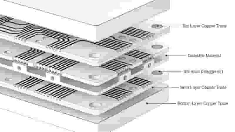
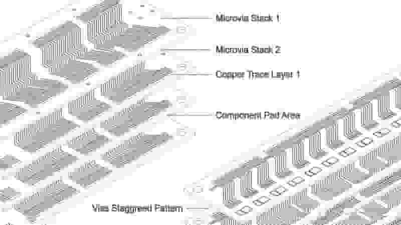
Microvias are arranged in stacked or staggered configurations to meet routing and reliability needs:
- Stacked: Aligned vertically for direct layer connections
- Staggered: Offset layout reduces mechanical stress and supports complex routing
Precision Drilling & Plating
Laser systems ensure tight positioning and consistent via diameter. Electroless and electroplating form void‑free copper inside each microvia for stable conductivity and thermal performance.
Microvias vs. PTH
| Feature | Microvias | PTH (Plated Through Holes) |
|---|---|---|
| Diameter | 0.13–0.38 mm | ≥0.5 mm |
| Layer Connection | Blind / Buried | Through all layers |
| Routing Density | Ultra High | Medium |
| Miniaturization | Excellent | Limited |
Microvia Reliability Factors
Microvias face thermal and mechanical stress in demanding environments. Key reliability factors include:
- Thermal Cycling: CTE mismatch between copper and laminate creates fatigue stress
- Capture Pad Design: Optimized pad size improves stability and lifetime
- Underfill & Encapsulation: Protects against moisture and thermal expansion
Strict DFM/DFR guidelines and AOI inspection ensure consistent quality for high‑reliability PCB applications.
Applications of Microvias
Microvias enable miniaturization and high performance across major industries:
- Consumer Electronics: Smartphones, wearables, tablets, and IoT devices
- Automotive: ADAS, infotainment, power control, and electrification
- Aerospace & Defense: Guidance systems, radars, and high‑vibration environments
- Medical Devices: Implants, ultrasound, and rigid‑flex PCBs

The Future of Microvias
Advancements in laser drilling and plating will enable smaller microvias with higher aspect ratios. HDI PCBs with 6–12+ layers will increasingly rely on microvias for space efficiency and electrical performance.
Flex‑rigid and advanced substrate designs will further expand the role of microvias in next‑generation electronics.
Conclusion
Microvias are indispensable for PCB miniaturization, high‑density routing, and reliable performance in modern electronics. From design to mass production, mature processes and strict quality control ensure microvia PCBs meet industrial and mission‑critical standards.
Get Your Microvia PCB Solution
Contact us for microvia PCB quotation, prototype, design support, and mass production.
Request Quote
Contact Engineer
How to Test a PCB for Short Circuit: Complete Professional Guide
PCB Manufacturing Capabilities

How to Select the Right Low-volume PCB Assembly Manufacturer

PCB Classification Guide: Types, Applications & Selection for Industrial Buyers
What is a Pad in PCB Design?