|

The Essentials of Microvias – Enabling Miniaturization in PCBs

Laser Drilled vs Photoimageable Microvias PCB

As printed circuit boards pack more components into smaller spaces, microvias enable advanced PCB miniaturization for HDI PCBs. We explain core technology, fabrication, types, reliability, and industrial applications for engineers and global buyers.

What Are Microvias

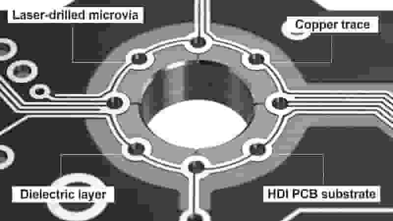
As printed circuit boards are designed to pack ever more components into compact spaces, manufacturers use microvias to enable PCB miniaturization. A microvia is a small laser‑drilled or photo‑imaged interconnect for high‑density HDI PCBs.

Typically 0.005–0.015 inches (0.13–0.38mm) in diameter, microvias reduce board thickness and layer count while preserving electrical performance. They enable greater functionality in shrinking devices including smartphones, wearables, and IoT hardware.
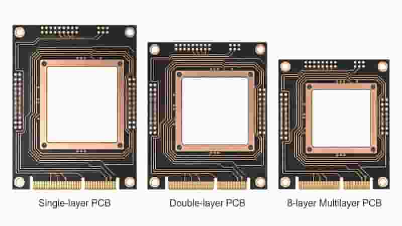
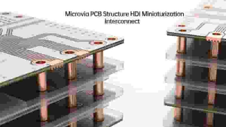
Microvia PCB Structure HDI Layers Miniaturization

Types of Microvias

Two main processes produce microvias for microvia PCB manufacturing: laser drilling and photoimaging.

Laser‑Drilled Microvias

Laser drilling uses YAG, CO₂, or excimer lasers to create microvias down to 0.005 inches. Benefits include high precision, small capture pads, and high depth‑to‑diameter ratios for multilayer HDI PCBs.

Photoimageable Microvias

UV patterning and copper plating form microvias at lower cost for lower‑density boards. Ideal for large panels where ultra‑fine features are not required.
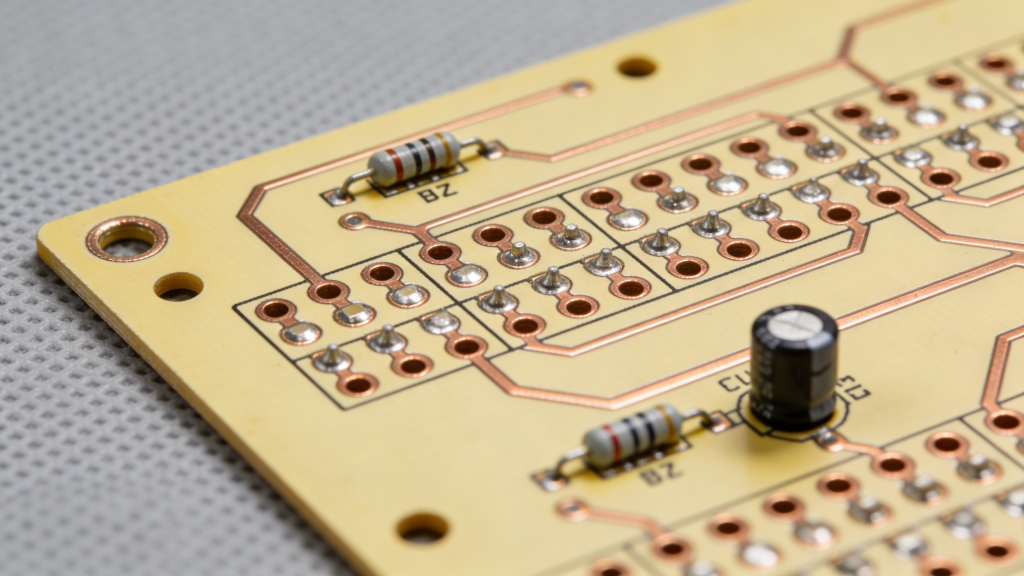
Laser Drilled vs Photoimageable Microvias PCB

Microvia PCB Technology

Reliable microvias require strict control of stacking, drilling, plating, and quality processes.

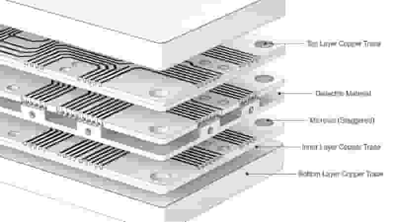
Stacked & Staggered Microvias

Stacked microvias align vertically to save space. Staggered microvias reduce mechanical stress for complex PCB miniaturization designs.

Precision Drilling & Plating

Controlled laser pulses and uniform copper plating ensure void‑free interconnections. Electroless and electroplating processes deliver consistent conductivity in microvia PCB production.
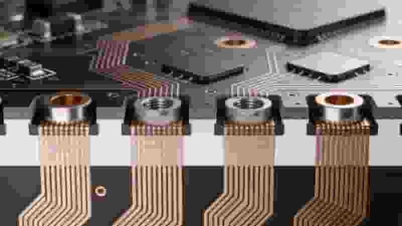
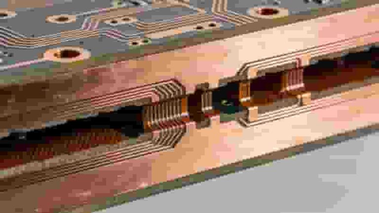
Stacked and Staggered Microvias PCB HDI Design

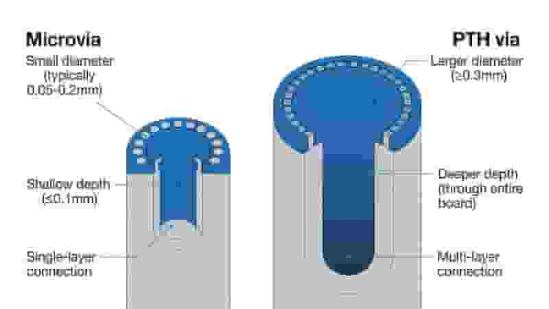
Microvias vs. PTH Vias

FeatureMicroviasPTH Vias
Size≤0.38mmLarger
Use CaseHDI PCBs, PCB miniaturizationStandard PCBs
Routing SpaceMaximizedLimited

Reliability Factors for Microvias

Microvias face thermal and mechanical stress in demanding environments. Key factors include CTE mismatch, capture pad design, and underfill protection. Proper DFM ensures long‑term performance for exported microvia PCB products.

Applications of Microvias

Microvias enable PCB miniaturization across high‑growth industries:

  • Consumer Electronics: Smartphones, wearables, IoT devices
  • Automotive: Advanced driver assistance and infotainment
  • Aerospace & Defense: Guidance and communication systems
  • Medical: Implants, ultrasound, and portable diagnostics
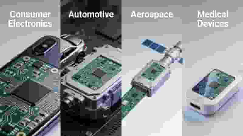
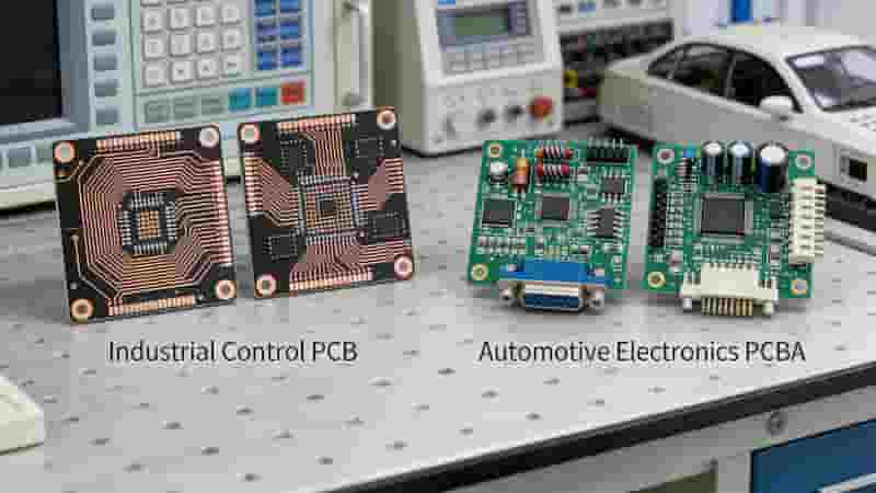
Microvia PCB Applications Consumer Automotive Medical Aerospace

Future of Microvias

Advances in laser drilling and plating will shrink microvias further and boost yields. Microvia PCB technology will remain essential for HDI PCBs and next‑generation PCB miniaturization in 5G, AI, and portable electronics.

Our Microvia PCB Capabilities

We specialize in high‑reliability microvia fabrication for global export. Our advanced laser drilling, strict quality control, and DFM optimization support volume production of HDI PCBs for industrial buyers worldwide.

  • Advanced laser drilling for precision microvias
  • IPC‑standard compliance for global markets
  • 100% AOI inspection for quality assurance
  • Rapid prototyping and mass production

Conclusion

Microvias are foundational to PCB miniaturization and HDI PCBs. By enabling smaller, lighter, higher‑performance boards, microvia technology supports innovation across every major electronics sector. For reliable, cost‑effective microvia PCB solutions, professional manufacturing and design expertise are critical.

Need Professional Microvia PCBs?

Contact us for a free quote, DFM analysis, and custom microvia PCB solutions for your global projects.

Request a Free Quote

True Quick Turn PCB Assembly Process and Standards

Quick Turn PCB Assembly in USA: The Strategic Guide to Speed, Cost & Reliability

Posted on
0 Comments
Quick Turn PCB Assembly is mission-critical for U.S. hardware teams racing to prototype, validate, and launch products without costly delays. This guide breaks down how to balance fast lead times, controlled costs, and industrial-grade reliability for American engineers, procurement teams, and OEMs. When Every Hour Counts For U.S. startups, medtech firms, and robotics developers, Quick…
PCB Solder Mask Cross Section Structure Diagram

PCB Solder Mask: The Complete Professional Guide to Solder Resist Technology

Posted on
0 Comments
This guide covers everything about PCB solder mask (solder resist), including its functions, types, colors, application processes, thickness standards, IPC testing, and assembly compatibility. Learn how solder mask protects circuits, prevents solder bridging, and improves reliability for industrial and high-density PCBs. We explain how to select the right solder resist for rigid, flexible, and high-speed…
Flexible PCB basic structure polyimide copper coverlay layers

Flexible PCB: Complete Materials, Design & Industrial Application Guide

Posted on
0 Comments
A flexible PCB (FPC) is a thin, bendable printed circuit that can fold, twist, and fit compact 3D spaces. This guide covers structure, materials, stack‑ups, design rules, manufacturing, and real‑world use cases to help global engineers and buyers select the right flex solution. Introduction In every new generation of electronic products, there is a clear…
PCB Layer Count Structure Thickness Diagram

Standard PCB Thickness: Complete Guide for Engineers & Buyers

Posted on
0 Comments
Standard PCB thickness is critical for mechanical strength, signal integrity, and assembly compatibility. This guide covers definitions, industry standards, influencing factors, manufacturing constraints, and design best practices for global industrial buyers. What Is Standard PCB Thickness The global standard PCB thickness is 1.57 mm (0.062 in), commonly referenced as 1.6 mm for simplicity. This is…
FR-4 PCB grade selection standard Tg high Tg halogen free

What is FR-4 Material in PCB Fabrication? The Complete Professional Guide

Posted on
0 Comments
FR-4 is the most widely used flame-retardant glass-epoxy laminate material for rigid PCB manufacturing. Defined by NEMA standards, it offers excellent electrical insulation, mechanical strength, thermal stability, and cost efficiency, making it the global industry standard for most electronic applications. What is FR-4 Material? FR-4 (Flame Retardant Grade 4) is a NEMA-defined material grade for…
Laser cutting nano coating SMT PCB stencil production process

Nano-Coated PCB Stencil Manufacturing for Precision & Durability

Posted on
0 Comments
Discover industry-leading performance with our nano-coated PCB stencils. Engineered to support high-precision SMT printing processes, professional nano surface treatment greatly improves stencil durability, stabilizes solder paste deposition quality, and cuts routine maintenance workload, helping your entire PCB assembly line run stably and efficiently. Why Choose Nano-Coated PCB Stencils For SMT Production Nano-coated SMT stencils deliver…

FAQs About HDI Microvia Definition, Types & Production Spec

A: Microvia is ultra-small interconnect mainly for HDI PCB, regular diameter 0.13~0.38mm, mostly manufactured by laser drilling.

A: Laser drilling for ultra-fine high-density microvia; photoimageable process with lower cost for common-density large batch production.

A: Stacked microvia aligns vertically to save layout space; staggered arrangement disperses layer stress to improve thermal and mechanical reliability.

A: Microvia tiny size for HDI miniaturized routing; PTH larger aperture runs full board thickness for through-hole component assembly and general interlayer connection.

A: CTE material mismatch, reasonable capture pad dimension, uniform inner copper plating and proper underfill protection against thermal cycling failure.

A: Smartphone & wearable device, automotive ADAS, aerospace communication equipment, portable medical diagnostic hardware and 5G IoT compact modules.

A: Small hole size greatly saves pad occupation area, maximizes inner routing space to realize high-density BGA escape wiring and thin-layer lightweight PCB design.

A: Further shrink microvia diameter, optimize laser drilling & electroplating craft to raise finished yield for high-end 5G and AI hardware HDI products.

Similar Posts