|

The Essentials of Microvias – Enabling Miniaturization in PCBs

Microvia PCB structure showing blind and buried vias for HDI PCB

Microvias are core interconnect structures that drive PCB miniaturization and high‑density design. This professional guide covers definitions, types, fabrication, reliability, applications and how we deliver high‑quality microvia PCB solutions for global industrial buyers.

What Are Microvias in PCBs

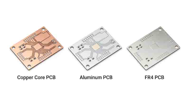
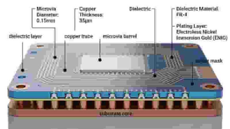
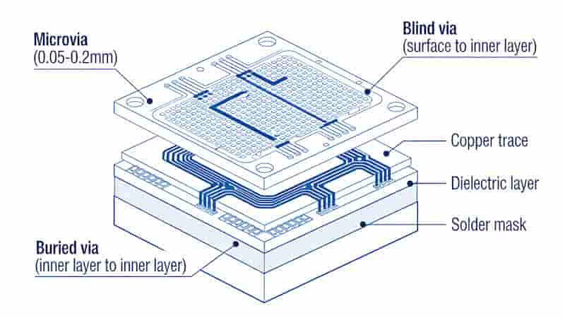
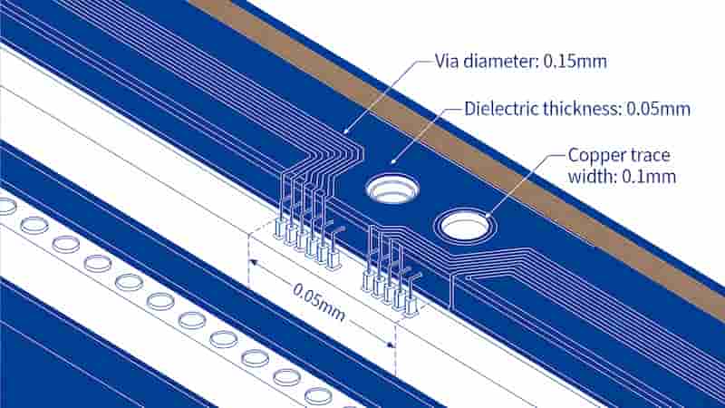
As printed circuit boards integrate more components into smaller spaces, microvias become essential for advanced PCB miniaturization. A microvia is a tiny vertical interconnect used in high‑density PCB designs, typically 0.005–0.015 inches (0.13–0.38mm) in diameter.

Compared with traditional through‑hole vias, microvias reduce board thickness and layer count while preserving electrical performance. They enable higher routing density and smaller form factors for smartphones, wearables, automotive controllers and medical devices.

Microvia PCB structure showing blind and buried vias for HDI PCB

Types of Microvias

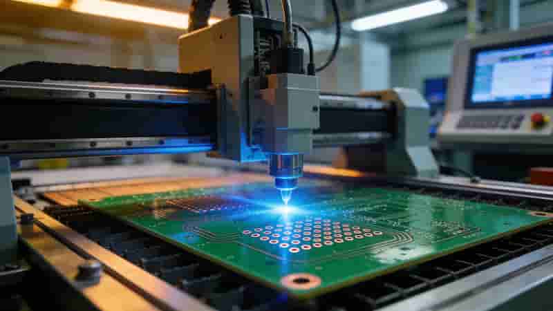
There are two mainstream processes for manufacturing microvias in PCB production: laser drilling and photoimageable technology.

Laser‑Drilled Microvias

Laser systems (CO₂, YAG, excimer) create precision microvias down to 0.005 inches. They support high depth‑to‑diameter ratios and fine capture pads, ideal for high‑density PCB designs.

  • High precision and small via annular rings
  • Depth‑to‑diameter ratio up to 15:1
  • Suitable for high‑layer‑count PCB

Photoimageable Microvias

UV patterning and copper plating form microvias at lower cost for moderate‑density boards. They support large production panels but have larger minimum feature sizes.

Laser drilled vs photoimageable microvias in PCB manufacturing

Microvia PCB Technology & Fabrication

Reliable microvia PCB production requires strict control of stacking, drilling, metallization and quality assurance.

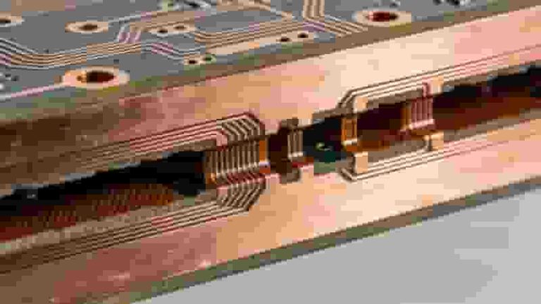
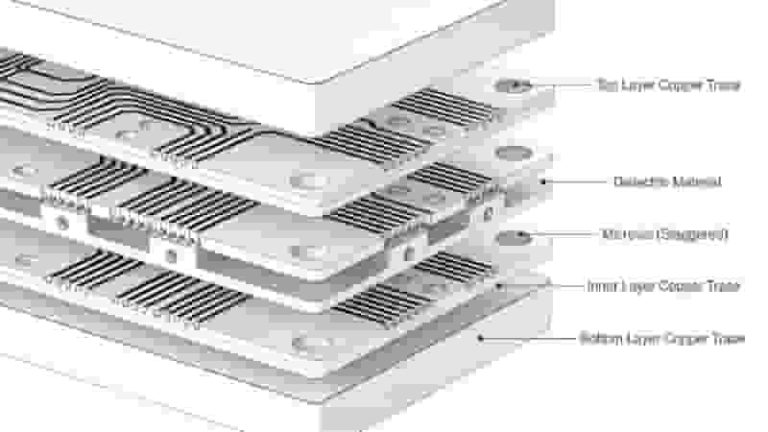
Stacked & Staggered Microvias

Stacked microvias align vertically to save space; staggered microvias offset positions to lower thermal stress and improve reliability.

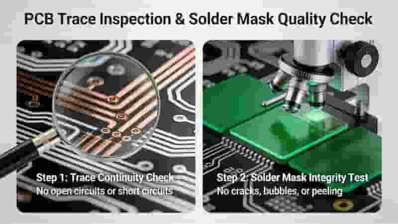
Plating & Quality Control

Electroless copper and electroplating ensure void‑free filling inside microvias. Statistical process control maintains consistent diameter, depth and plating quality.

Microvia PCB fabrication process including laser drilling and copper plating

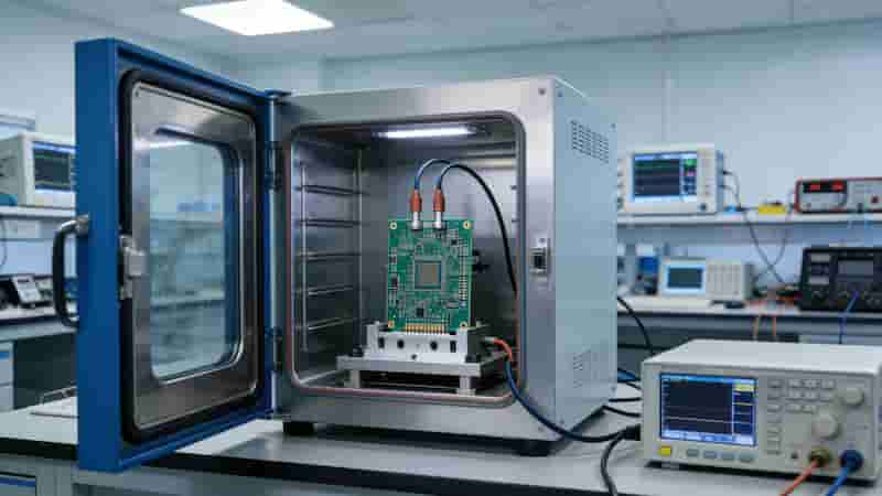
Microvia Reliability Factors

Microvia durability depends on thermal cycling, pad design, materials and assembly protection.

  • CTE mismatch between copper and laminate
  • Optimized capture pad size for microvias
  • Underfill and encapsulation to improve stability
Microvia PCB reliability under thermal cycling and mechanical stress

Industry Applications of Microvia PCBs

Microvia PCBs are widely used in industries demanding miniaturization and high performance:

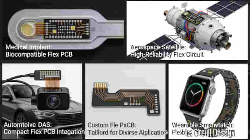
  • Consumer Electronics: smartphones, tablets, wearables
  • Automotive: ADAS, infotainment, power control
  • Aerospace & Defense: guidance systems, high‑reliability modules
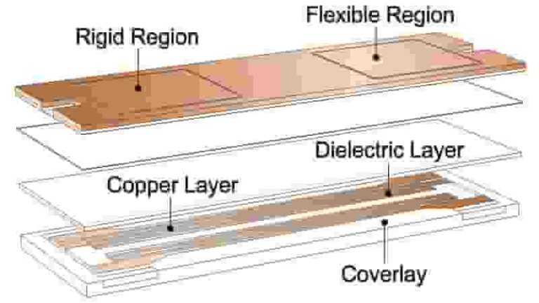
  • Medical Devices: implants, diagnostic equipment, rigid‑flex PCB

The Future of Microvias in PCB Design

Advances in laser drilling and plating will enable smaller microvias with higher aspect ratios. Microvia technology will continue supporting 6–12+ layer HDI boards, AI hardware and high‑speed computing applications.

Our Microvia PCB Manufacturing Capabilities

We specialize in high‑precision microvia PCB design, prototyping and mass production for global buyers. Our advanced laser drilling systems, strict quality inspection and engineering expertise ensure stable performance and competitive costs.

  • Advanced laser drilling for microvias down to 0.13mm
  • Stacked / staggered microvia design support
  • 100% AOI and electrical testing for reliability
  • Fast prototypes and volume export production

Summary

Microvias are foundational to PCB miniaturization and high‑density interconnect design. They deliver smaller size, higher performance and greater reliability for modern electronics. As a professional PCB manufacturer, we provide customized microvia PCB solutions to meet your engineering and commercial requirements.

Get Your Microvia PCB Quote Today

Contact us for custom design, prototype and mass production of high‑quality microvia PCBs.

Inquire Now | Custom Quote

PCB Manufacturability Analysis Software Interface DFA Check

Design for Manufacturability and Assemblability of Printed Circuit Board

Posted on
0 Comments
Optimize your PCB design for high yield, low cost, and reliable assembly with industry-leading DFM and DFA principles aligned with IPC standards. What is Design for Manufacturing Design for Manufacturing, also known as concurrent or simultaneous engineering, focuses on the relationship between product physical design and manufacturing systems. By integrating DFM principles into product design,…
PCB Material Comparison FR4 Rogers Aluminum Ceramic

Key Factors Influencing Custom PCB Costs in 2025 

Posted on
0 Comments
Custom PCB costs in 2025 are shaped by material selection, layer count, board dimensions, manufacturing processes, surface finish, order volume, tolerances, certifications, and global supply chains. This professional guide breaks down all cost drivers with technical details, comparison tables, and actionable cost‑saving strategies for industrial buyers, engineers, and importers. PCB Base Material & Cost Impact…
Custom Flex PCB Manufacturing Design Fabrication Assembly Testing

Custom Flex PCB: Tailored Solutions for Your Applications

Posted on
0 Comments
Custom Flex PCB delivers highly flexible, space‑optimized interconnects for medical, automotive, aerospace, wearable, and industrial electronics. We provide end‑to‑end tailored flex circuit solutions from design and material selection to fabrication, assembly, and reliability testing to match your exact application needs. The Essence of Custom Flex PCBs Custom Flex PCB boards are built on flexible substrates…
PCB trace inspection and solder mask quality check

How to Judge PCB Quality: 7 Expert Tips for Reliable Boards

Posted on
0 Comments
Master how to judge PCB quality with IPC‑aligned inspection tips. Check traces, capacitors, grounding, and testing to ensure durable, high‑performance circuit boards. PCBs are the foundation of all electronic devices. Learning how to judge PCB quality directly prevents failures, reduces costs, and ensures long‑term reliability for industrial, automotive, medical, and 5G applications. We share 7…
Metal Core PCB cross section structure aluminum copper thermal dielectric layer

Standard PCB Thickness: Complete Guide for Engineers & Buyers

Posted on
0 Comments
Standard PCB thickness is critical for mechanical strength, signal integrity, and assembly compatibility. This guide covers definitions, industry standards, influencing factors, manufacturing constraints, and design best practices for global industrial buyers. What Is Standard PCB Thickness The global standard PCB thickness is 1.57 mm (0.062 in), commonly referenced as 1.6 mm for simplicity. This is…
Copper Core PCB FAQ custom PCB manufacturing inquiry

What is Copper Core PCB? Comprehensive Overview, Advantages & Industry Insights

Posted on
0 Comments
This guide gives a complete introduction to Copper Core PCBs, explaining their structure and unique advantages over standard FR4 and aluminum boards. Learn how copper core technology delivers superior thermal management, reliability, and electrical performance—making it ideal for high‑power, automotive, and industrial electronics. Explore types, design principles, manufacturing, FAQs, and how to select the right…

FAQs About PCB Microvia Type, Fabrication & Application Standard

A: Mini vertical interconnect for HDI PCB, usual diameter 0.13~0.38mm, substitute big-size PTH to realize circuit miniaturization and high-density wiring.

A: Laser drilling for ultra-small hole & high aspect ratio high-end HDI; photoimageable process cost-efficient for medium-density batch production with bigger minimum aperture.

A: Stacked vertically aligned to save layout space; staggered position offset to reduce CTE thermal stress and lift risk for better long-term reliability.

A: Complete electroless copper seed layer plus electrolytic copper filling to avoid inner void and ensure full conductive interconnection inside microvia.

A: CTE mismatch between copper and substrate, unreasonable capture pad dimension, insufficient via filling and thermal cycling working environment.

A: Smartphone mainboard, wearable equipment, automotive ADAS module, precision medical device and aerospace high-density rigid-flex PCB.

A: Full AOI appearance inspection, electrical continuity test and sampling cross-section check to verify inner copper filling status of microvias.

A: Continually shrinking via diameter, higher aspect ratio, widely applied on high-layer HDI, AI computing mainboard and high-speed communication hardware.

Similar Posts