|

Understanding Plated Half-Holes (Castellated Holes) in PCB Design

Cross Section of Plated Half Hole PCB

Plated half-holes, also called castellated holes, provide a space-efficient way to interconnect separate PCB modules by soldering. Unlike bottom pads, their edge positioning simplifies mounting and enhances reliability. This article explains everything about plated half-hole structures, design guidelines, manufacture, benefits and use cases.

Structure of Plated Half-Holes

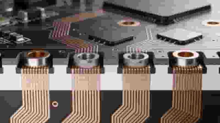
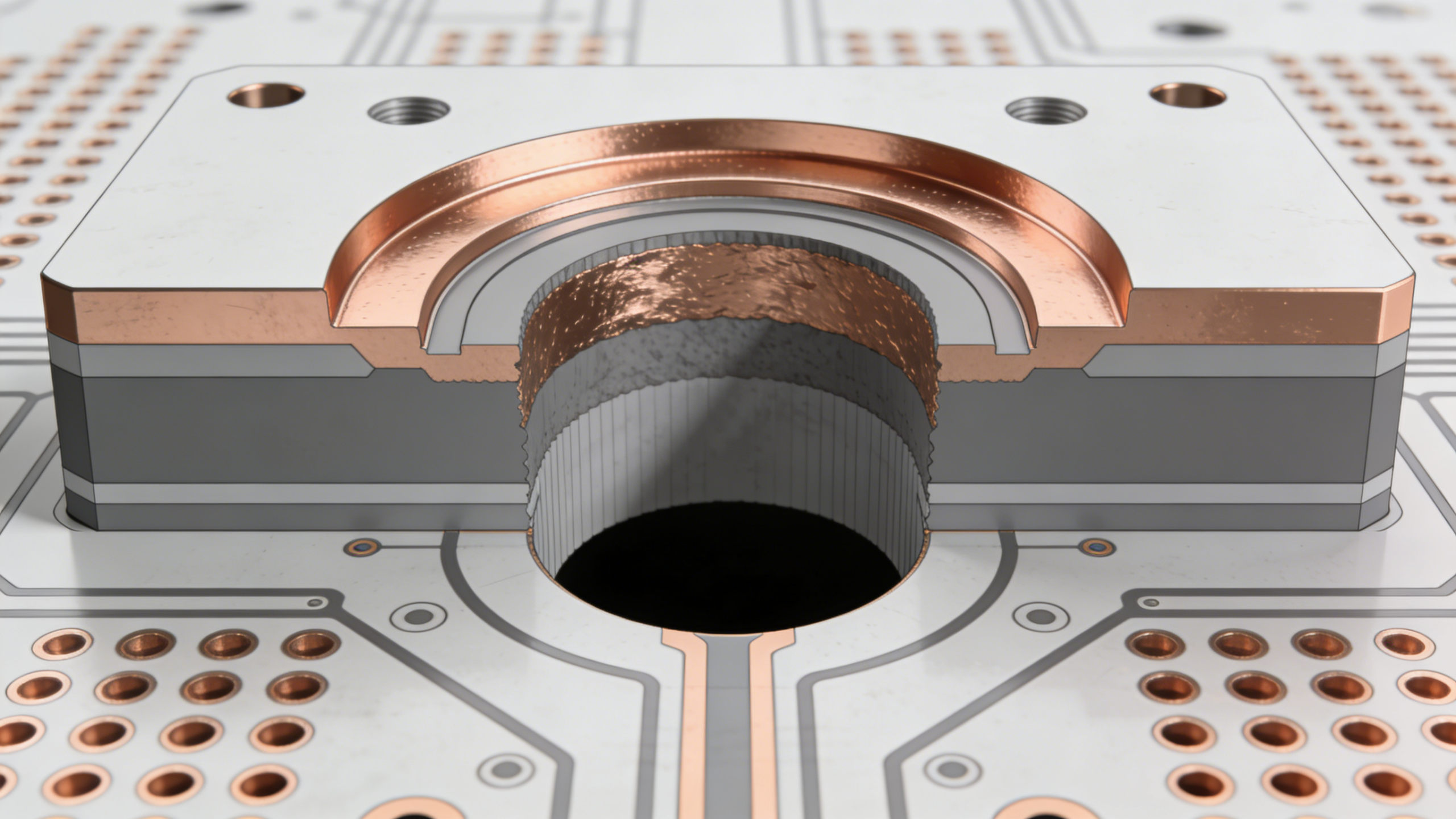
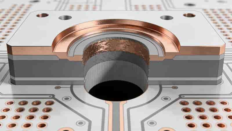
Plated half-holes, also known as castellated holes, resemble plated through-holes in structure but occupy only half the vertical space. As illustrated below, they plate the walls on one side of the hole.

Half-holes connect individual PCB modules to main boards via soldering. Compared to under-module pads, they improve joint access and coaxial alignment. Half-holes also facilitate modular board assembly and high-density interconnects.

Plated Half Hole PCB Structure Diagram

Design Guidelines

When designing plated half-holes, consider the following critical factors:

  • Position precisely on board edges for easy accessibility
  • Define as plated through-holes in EDA tools
  • Include in drill files for manufacturer
  • Add pads on each layer for stability
  • Mind minimum sizing based on board thickness
  • Choose half-hole diameters balancing via reliability, routing spaces, and costs
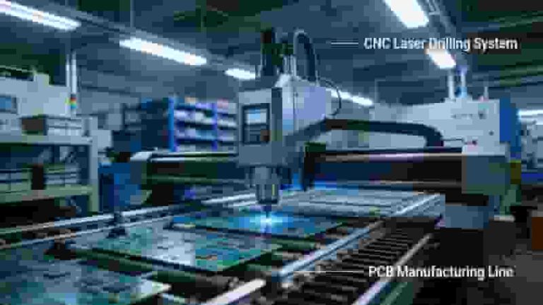
Fabrication Process

Traditional processes have limitations in productivity and performance. Newer methods utilize specialized drilling on panel edges and direct copper plating to boost efficiency. One-step solutions like precision laser cutting also exist for high-precision castellated holes.

Cross Section of Plated Half Hole PCB

Key Benefits

Half-holes simplify soldering, measurement, and inspection versus bottom-located pads. Their edge positioning enhances coaxiality while avoiding dust traps. Half-holes also reduce via filler challenges and enable flexible routing options for modern PCB designs.

Applications

  • Modular boards
  • Changing component layouts
  • High-density interconnections
  • Validating solder joint quality
  • Bridging rigid-flex PCB sections

Plated half-holes continue finding increased applications in complex modular PCB designs due to their flexibility and reliability.

Conclusion

Incorporating plated half-holes in suitable designs allows improving interconnect accessibility, manufacturability, and reliability. We hope this overview aids your learning. Please reach out with any questions!

Need Custom Plated Half-Hole PCBs?

We provide professional PCB manufacturing, DFM analysis, and reliable assembly for castellated hole modules. Get a free quote today.

Contact Us for a Quote

Metal Core PCB cross section structure aluminum copper thermal dielectric layer

Standard PCB Thickness: Complete Guide for Engineers & Buyers

Posted on
0 Comments
Standard PCB thickness is critical for mechanical strength, signal integrity, and assembly compatibility. This guide covers definitions, industry standards, influencing factors, manufacturing constraints, and design best practices for global industrial buyers. What Is Standard PCB Thickness The global standard PCB thickness is 1.57 mm (0.062 in), commonly referenced as 1.6 mm for simplicity. This is…
Turnkey PCB Manufacturing Quality Control AOI X-ray Inspection

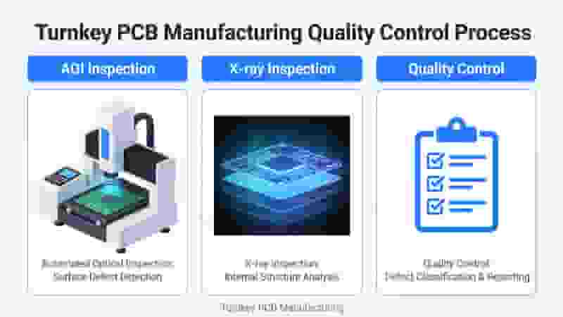
Turnkey PCB Manufacturing and Assembly: Full One-Stop Solution Advantages

Posted on
0 Comments
Turnkey PCB manufacturing and assembly provides a fully integrated end-to-end service covering design for manufacturing (DFM), bare board fabrication, electronic component sourcing, SMT assembly, THT assembly, functional testing, quality inspection and global shipping. This unified model reduces lead times, lowers total costs, improves quality consistency and simplifies project management for international electronics buyers, engineers and…
Rigid-Flex PCB Stackup Overview Layer Structure Diagram

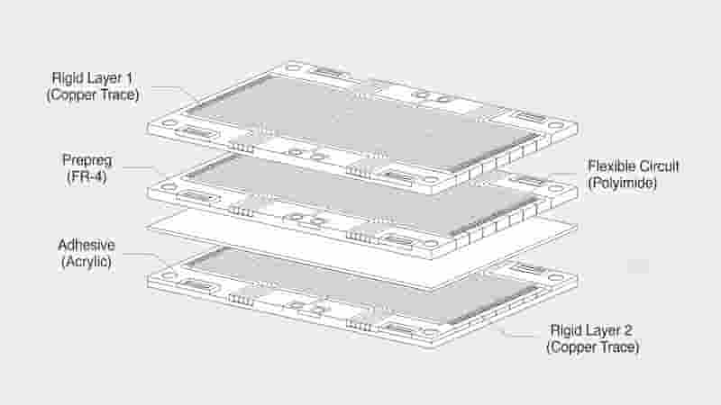
Rigid-Flex PCB Stackup: Professional Design & Manufacturing Guide 

Posted on
0 Comments
Rigid-Flex PCB Stackup is the core of high-performance rigid-flex circuit boards, directly determining reliability, flexibility, signal integrity and service life. This guide covers layer structure, material selection, impedance control, DFM rules, common stackup examples and manufacturing standards for engineers and procurement teams. What Is Rigid-Flex PCB Stackup Rigid-Flex PCB Stackup defines the layered arrangement of…
PCB Assembly Service SMT THT Turnkey

Affordable PCB Prototypes & Assembly Services

Posted on
0 Comments
We provide high-quality, low-cost PCB fabrication and PCB assembly for engineers, procurement teams, and global buyers. From 2-layer to multilayer and flexible PCBs, we deliver fast, reliable solutions tailored to your project requirements. Why Choose Us for Low-Cost PCB Prototypes We combine affordable PCB prototypes with consistent quality and professional support. As a reliable manufacturer,…
FR4 PCB layer structure fiberglass epoxy copper

Aluminum PCB vs FR4 PCB: Full Technical Comparison for Industrial & Export Buyers

Posted on
0 Comments
This professional guide compares Aluminum PCBs and FR4 PCBs in thermal performance, electrical properties, mechanical strength, cost, and ideal applications to help engineers and purchasers select the right PCB for reliable export projects. What is FR4 PCB FR4 PCB is the most widely used rigid PCB material, made of woven fiberglass cloth bonded with flame‑resistant…
Selective Wave Soldering Machine for PCB Assembly Process

Selective Wave Soldering Guidelines: Process, Parameters & Best Practices for PCB Assembly

Posted on
0 Comments
Selective wave soldering is a precision soldering method designed for mixed-technology PCBs, protecting heat-sensitive components while delivering reliable through-hole solder joints. This professional guide covers core principles, process flow, critical parameters, DFM rules, defect resolution, and quality control for industrial PCB manufacturing. 1. Overview of Selective Wave Soldering The two primary process technologies in PCB…

FAQs About PCB Plated Half Hole (Castellated Hole)

A: It is half-cut PTH arranged on PCB edge with half copper-plated hole wall, used for module board soldering connection with main motherboard.

A: Better soldering accessibility, higher assembly coaxial precision, easy solder joint inspection and no hidden dust accumulation gap.

A: Place strictly on board outline edge, set as PTH in design software, add full-layer pads and define related parameters inside drill drawing.

A: Edge special routing cutting after full hole drilling & plating; high-precision laser cutting is available for high-demand small batch products.

A: Modular pluggable sub-board, rigid-flex transition connection, interchangeable functional module and high-density embedded interconnect design.

A: Edge-mounted structure saves inner pad space, reduces inner via occupation and leaves more layout area for dense signal routing.

A: Yes, direct solder via edge half-hole realizes module fixed connection to eliminate extra connector and cut overall BOM cost.

A: Complete Gerber layer files, accurate drill file and clear mechanical outline drawing marking all castellated hole positions.

Similar Posts