Copper Core PCB delivers superior thermal conductivity and stability for high-power electronics, while Metal Core PCB offers cost-effective thermal management for general industrial and commercial applications.
Introduction to PCB Technology
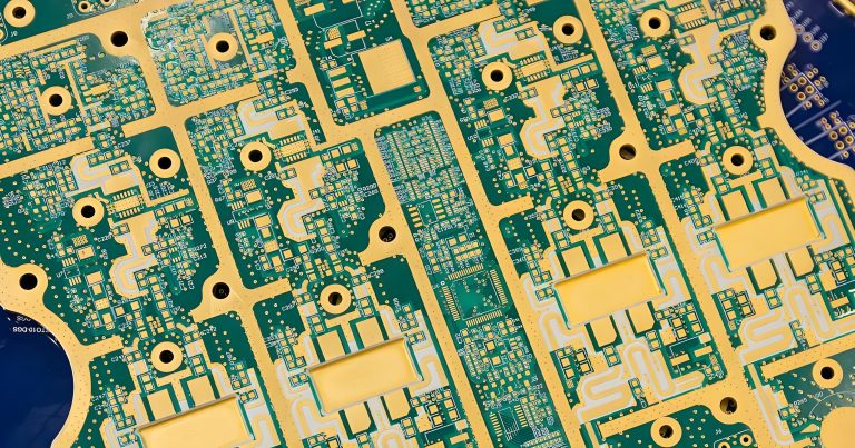
Printed Circuit Boards (PCBs) are the foundational building blocks of modern electronic devices. From consumer electronics to industrial machinery, PCBs ensure reliable electrical connectivity and mechanical support for components.
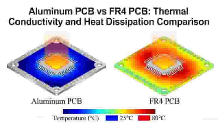
As devices become more compact and powerful, thermal management has become critical. This has driven the development of advanced substrates like Metal Core PCB and Copper Core PCB to handle higher heat loads.
What is a PCB?
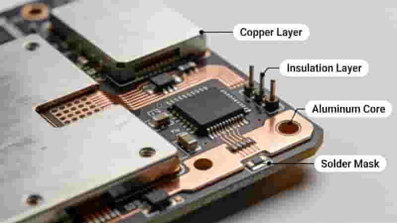
A PCB mechanically supports and electrically connects electronic components using conductive copper tracks, pads, and features etched from copper sheets laminated onto a non-conductive substrate.
Evolution of PCB Materials
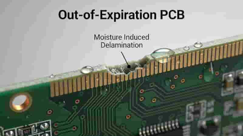
Traditional FR-4 PCBs work well for low-power applications but lack sufficient thermal conductivity for high-power designs. The limitations of FR-4 led to the development of Metal Core PCB and Copper Core PCB to improve heat dissipation and reliability.
Overview of Metal Core PCBs (MCPCBs)
What is a Metal Core PCB?
A Metal Core PCB uses a metal base (typically aluminum, copper, or steel) below the dielectric and circuit layers to efficiently dissipate heat.
Common Materials Used in MCPCBs
Aluminum is the most widely used material for Metal Core PCB due to its light weight, low cost, and reasonable thermal conductivity. Copper and steel are used for specialized applications.
Applications of Metal Core PCBs
Metal Core PCBs are widely used in LED lighting, automotive electronics, power converters, and telecommunications equipment where cost-effective thermal management is needed.
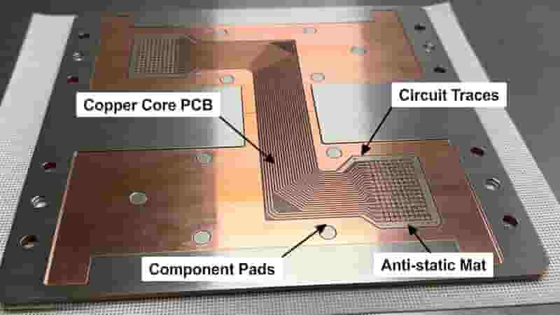
Understanding Copper Core PCBs (CCPCBs)
What Makes Copper Core PCBs Unique?
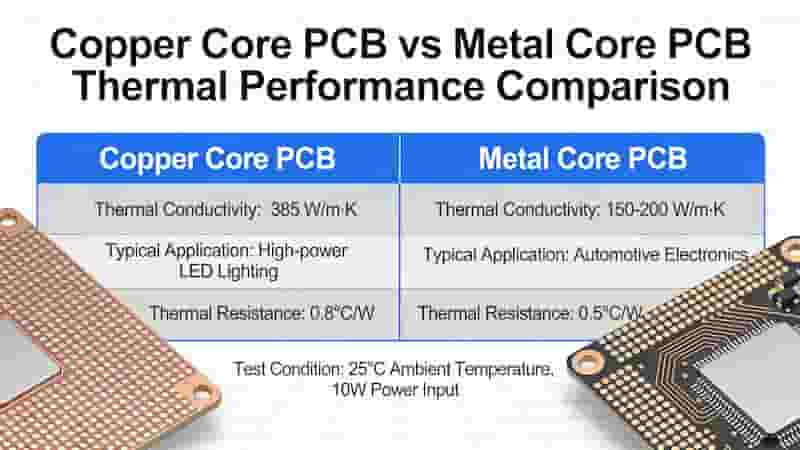
Copper Core PCB features a pure copper base with thermal conductivity of 385–400 W/m·K, far exceeding aluminum-based Metal Core PCB.
Key Features of Copper Core PCBs
Copper Core PCB offers excellent mechanical strength, low thermal expansion, and superior electrical conductivity, making it ideal for high-power, high-frequency, and mission-critical applications.
Applications of Copper Core PCBs
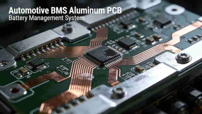
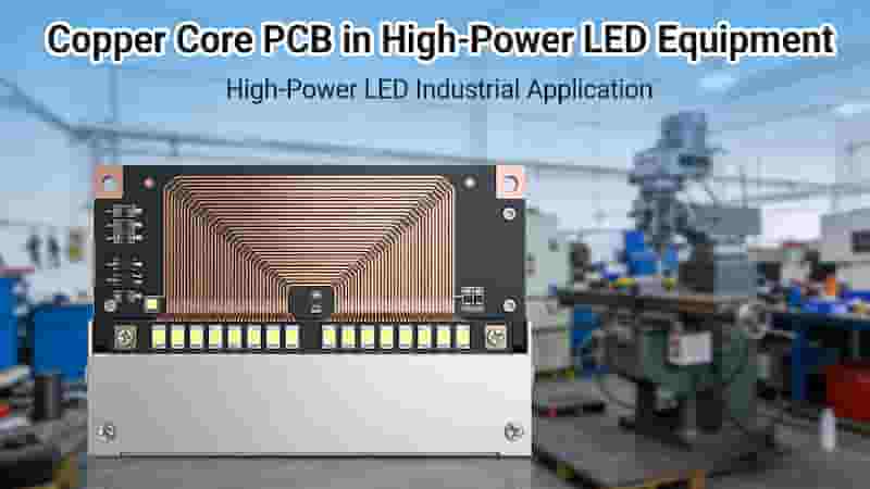
Copper Core PCBs serve aerospace, defense, industrial automation, high-power LEDs, laser systems, and electric vehicle power modules.
Copper Core PCB vs. Metal Core PCB: Detailed Comparison
| Parameter | Copper Core PCB | Metal Core PCB (Aluminum) |
|---|---|---|
| Thermal Conductivity | 385–400 W/m·K | 150–235 W/m·K |
| Cost | Higher | Lower to Moderate |
| Weight | Heavier | Lighter |
| Electrical Stability | Excellent | Good |
| Mechanical Strength | Very High | Moderate |
| Typical Applications | Aerospace, Power Modules | LED, Automotive, Telecom |
Thermal Conductivity
Copper Core PCB has nearly double the thermal conductivity of aluminum Metal Core PCB, providing far better heat dissipation for high-power devices.
Cost & Manufacturing
Copper Core PCB involves more complex manufacturing, leading to higher cost. Metal Core PCB (aluminum) is easier to produce and more affordable for mass production.
Electrical & Mechanical Performance
Copper Core PCB provides superior electrical conductivity and mechanical stability under thermal cycling. Metal Core PCB offers sufficient performance for most general applications.
Pros & Cons of Copper Core & Metal Core PCBs
Pros and Cons of Copper Core PCBs
✔ Unmatched thermal conductivity
✔ Excellent electrical performance
✔ High mechanical strength & stability
✘ Higher cost
✘ Heavier weight
Pros and Cons of Metal Core PCBs
✔ Cost-effective
✔ Lightweight
✔ Easy manufacturing & assembly
✔ Good thermal management for general use
✘ Lower thermal conductivity than copper
Choosing Between Copper Core and Metal Core PCBs
Choose Copper Core PCB if you need maximum thermal performance, high current capacity, and long-term reliability for high-power, aerospace, defense, or industrial applications.
Choose Metal Core PCB if you need a cost-effective, lightweight solution for LED lighting, automotive electronics, power supplies, and general industrial equipment.
Future Trends in PCB Materials
The industry is moving toward hybrid metal-composite cores, graphene-enhanced substrates, and nano-ceramic dielectrics to further improve thermal performance, reduce weight, and lower costs for both Copper Core PCB and Metal Core PCB technologies.
Conclusion
Copper Core PCB and Metal Core PCB both solve critical thermal challenges in modern electronics. Copper Core PCB leads in performance for demanding applications, while Metal Core PCB provides a practical, budget-friendly solution for mainstream designs.
Selecting the right PCB type ensures optimal performance, reliability, and cost efficiency for your electronic project.
Get Custom PCB Solutions & Free Quote
We provide professional Copper Core PCB and Metal Core PCB design, manufacturing, and assembly for global industrial buyers. Contact us today for a fast, accurate quotation and technical support.
Contact Us for Inquiry & Custom PCB Quote
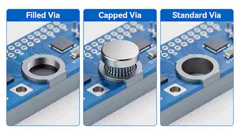
Filled and Capped Vias: Boost PCB Reliability for Industrial & Export Applications
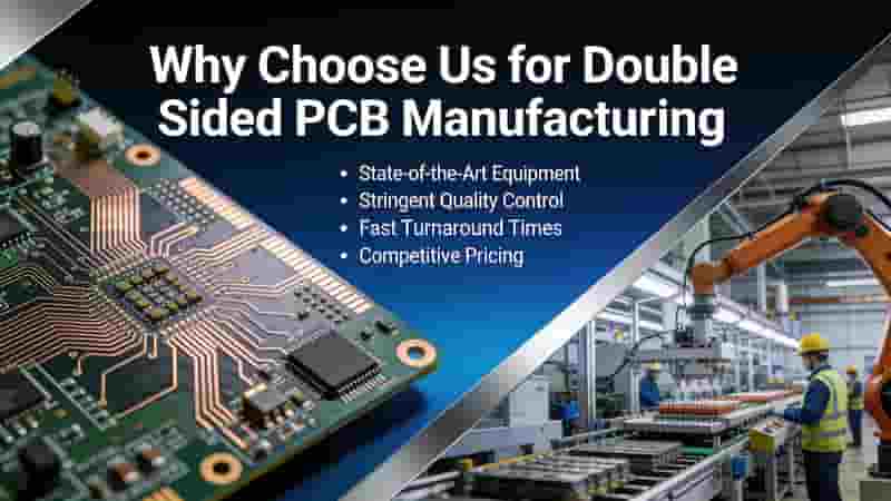
Why Choose Us for Double Sided PCBs?
How to Find Reliable China PCB Manufacturers: 5 Critical Vetting Tips
Through-hole PCB Assembly Service | IPC Certified THT PCBA Solutions
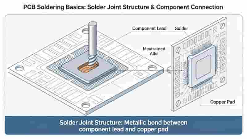
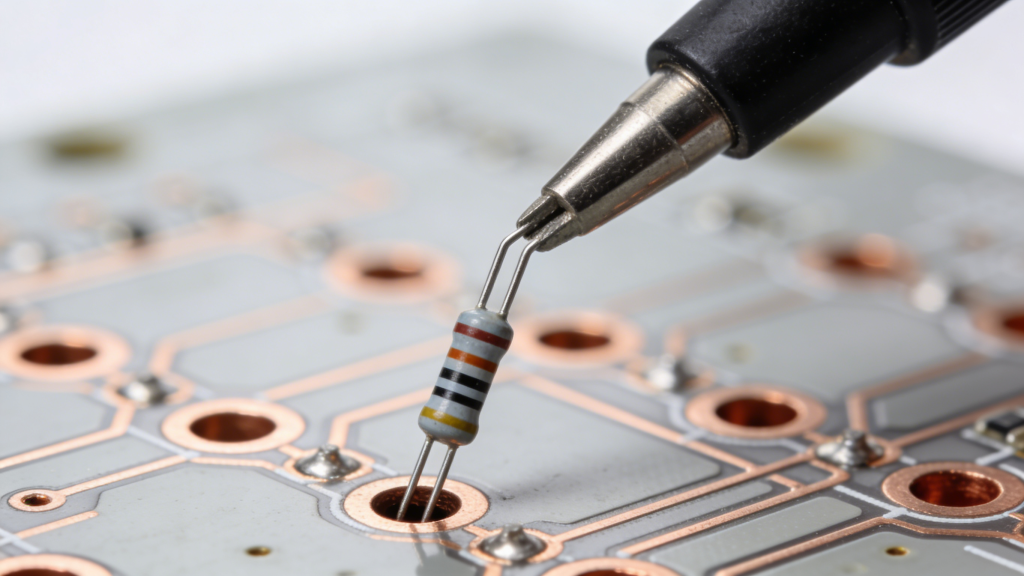
How to Solder on PCB: Essential Techniques and Best Practices for Reliable Assembly