|

Flexible PCB Stiffeners: Materials, Benefits & Industrial Uses

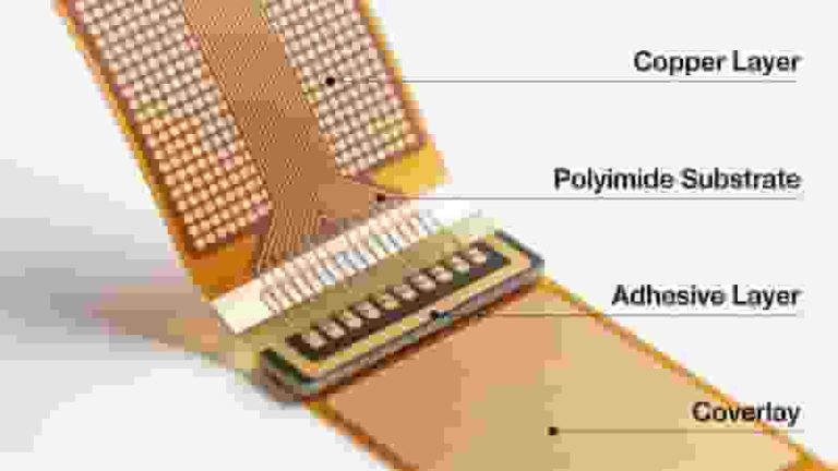
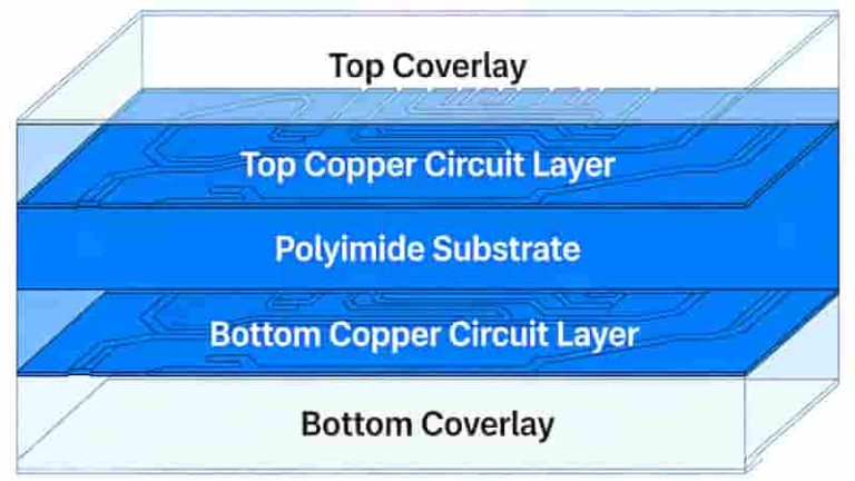
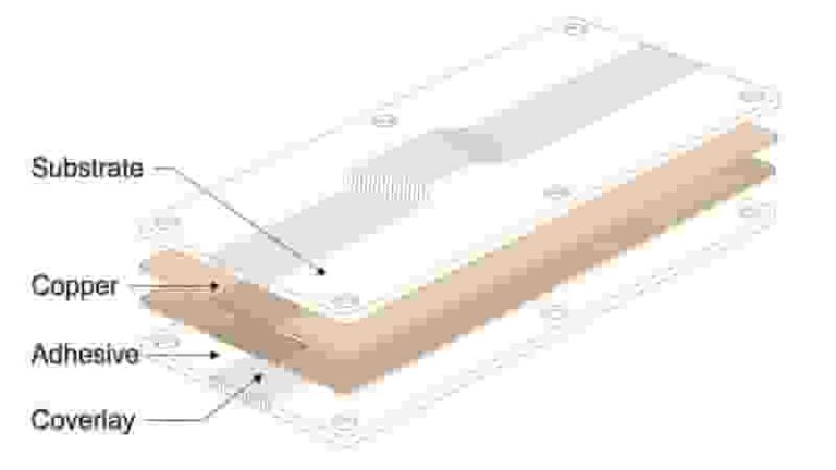
Flexible PCB Stiffener Overview Structure

Flexible PCB stiffeners add targeted rigidity to flex & rigid‑flex circuits, improving SMT yield, protecting components, stabilizing connectors, and extending service life. This professional guide covers materials, selection, design rules, and applications for global engineers and buyers.

What Are Flexible PCB Stiffeners

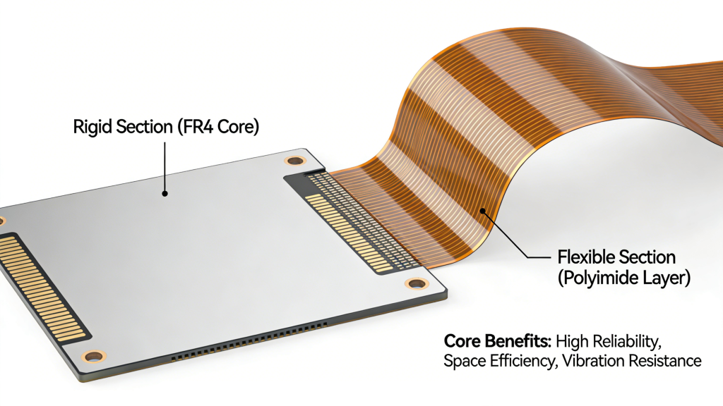
Flexible PCB stiffeners are non‑conductive reinforcement layers bonded to specific areas of flex circuits or rigid‑flex PCBs. They preserve overall flexibility while adding localized rigidity to prevent damage, improve assembly, and ensure reliable performance.

These components solve critical failure points: solder joint cracking, component misalignment, unstable ZIF connectors, and handling damage during manufacturing. They comply with IPC‑2223 standards and are widely used in 5G, medical, automotive, and aerospace electronics.
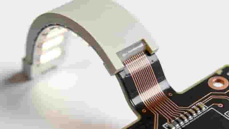
Flexible PCB Stiffener Overview Structure

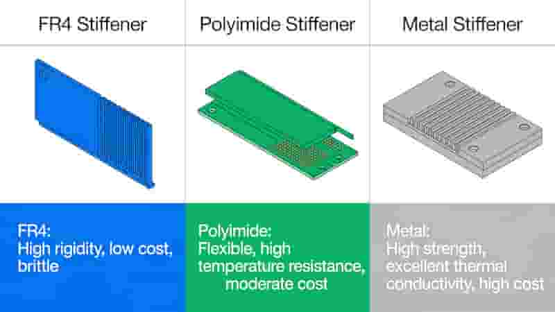
Stiffener Materials Comparison

MaterialCostStrengthHeat DissipationBest For
FR4LowHighModerateSMT/PTH support, general use
Polyimide (PI)MediumModerateLowZIF connectors, high‑precision
Stainless Steel / AluminumHighVery HighExcellentThermal management, high stress
Flex PCB Stiffener Materials FR4 PI Metal

Core Benefits of Flex PCB Stiffeners

1. Enhance Durability: Reduce flex‑induced stress and extend PCB lifespan in dynamic environments.

2. Stabilize Components & Connectors: Provide rigid surfaces for SMT assembly and ensure precise ZIF connector fit.

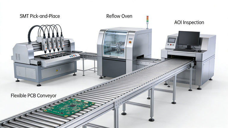
3. Improve Assembly Yield: Enable reliable pick‑and‑place and reflow soldering, lowering production defects.

4. Meet Industry Standards: Support compliance with IPC‑2223 for medical, aerospace, and automotive use cases.
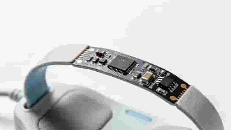
Flex PCB Stiffener Benefits Durability Assembly SMT

Industrial Applications

Flexible PCB stiffeners are essential in high‑reliability sectors:

Medical Devices: Wearables, diagnostic tools, and implantable components requiring stable connections.

5G & Telecom: High‑frequency modules needing thermal control and structural stability.

Aerospace & Automotive: Vibration‑resistant reinforcement for radar, ECU, and in‑vehicle systems.

Consumer Electronics: Foldable screens, smartwatches, and wireless earbuds for consistent performance.
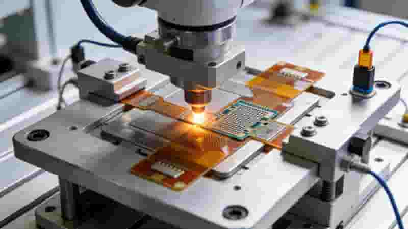
Flex PCB Stiffener Applications Medical Automotive 5G

Material & Thickness Selection

Choose flexible PCB stiffeners based on application demands:

FR4: 0.08–3.18 mm, ideal for cost‑effective SMT support.

Polyimide (PI): 25–125 µm, perfect for ZIF connector precision.

Metal: 0.1–0.45 mm, used for heat dissipation and heavy loads.

Always match thickness to connector specs and environmental stress to avoid failure.

Bonding & Assembly Methods

PSA (Pressure Sensitive Adhesive): Low‑cost, easy to apply, ideal for prototypes and consumer devices.

Thermal Bonding: Permanent, high‑strength bond for aerospace, medical, and harsh environments.

We follow strict bonding processes to ensure flexible PCB stiffeners perform reliably over the product lifecycle.

Conclusion

Flexible PCB stiffeners are critical to maximizing reliability, assembly efficiency, and service life of flex and rigid‑flex circuits. Selecting the right material, thickness, and bonding method ensures your design meets industrial performance and compliance requirements.

Get Custom Flexible PCB Stiffener Solutions

Contact us for professional stiffener design, material selection, and full flex PCB manufacturing support.

Request Quote & Consultation
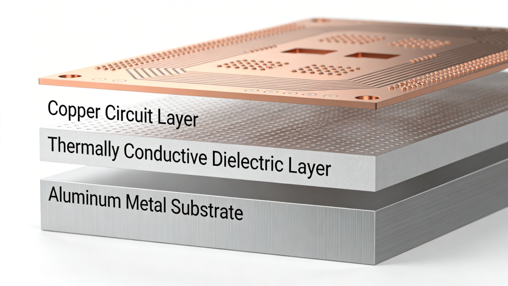
Flexible PCB fabrication process flow chart

Flexible PCB Manufacturing and Assembly: The Complete 2025 Guide
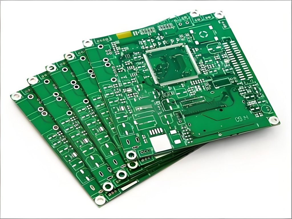
Posted on
0 Comments
This professional guide covers flexible PCB materials, fabrication, SMT assembly, quality control, and best practices for engineers, buyers, and global importers. Learn how to ensure reliability, consistency, and cost efficiency for your flex PCB projects. Why Choose Flexible PCBs? Flexible PCB devices offer distinct advantages over rigid PCBs, making them ideal for modern electronics with…
Through-hole Technology THT PCB Component Insertion

Through-hole PCB Assembly Service | IPC Certified THT PCBA Solutions

Posted on
0 Comments
We provide reliable through-hole PCBAs assembly service for industrial, power, medical, aerospace and automotive applications. Our IPC-standard THT assembly supports prototypes to mass production with wave soldering, selective soldering and full inspection. Through-hole PCB Assembly Service Overview Our through-hole PCB assembly fulfills leaded assembly demands across industries. We deliver single-sided, double-sided and high-density multilayer through-hole…
HDI PCB Microvia, Blind & Buried Via Structure

HDI PCB Manufacturing – Microvia, Blind & Buried Via HDI Boards up to 30 Layers

Posted on
0 Comments
HDI PCB manufacturing provides high-density interconnect solutions with microvia, blind via, and buried via structures for compact, high-performance electronics. We deliver reliable HDI boards from prototype to mass production, supporting up to 30 layers for automotive, 5G, medical, and industrial applications. What Is HDI PCB and Why Choose It High-density interconnect (HDI) PCBs offer much…
Multilayer PCB manufacturing process flowchart from design to final inspection

Multilayer PCB Prototyping & Manufacturing Services | Fast & Reliable

Posted on
0 Comments
Explore multilayer PCBs: their structure, benefits, and applications. We deliver fast, high-quality multilayer PCB manufacturing and prototyping services for global industrial buyers and engineers. What is a Multilayer PCB? A multilayer PCB features three or more copper layers, unlike single-layer PCBs with just one. Components are placed on the outer surface layers, while inner layers…
PCB Order Process Flow for Prototyping Fabrication Assembly

How to Order PCB Prototyping, Fabrication & Assembly Services in China

Posted on
0 Comments
Get a clear quote within 24 hours and receive high-quality PCB prototypes in as fast as 3-5 days, with one-to-one engineering support from inquiry to delivery. Get a Free Quote Now 24h quotation · 3-5 day PCB prototyping · One-stop PCB & PCBA Why Engineers and Buyers Choose Us From fast PCB prototypes to full…
Metal Core PCB Thermal Dissipation Structure

How to Choose the Best Metal Core PCB Manufacturer for Your Project

Posted on
0 Comments
If you’re wondering how to choose the best metal core PCB manufacturer for your project, you’re in the right place. Selecting the right supplier is critical for high-power applications like LED lighting, automotive systems, and power supplies. Why Choosing the Right Metal Core PCB Manufacturer Is Critical In modern electronics, metal core PCBs deliver superior…

FAQs About FPC Stiffener Material, Selection & Bonding Process

A: Partial reinforcement to fix connector and component area, avoid solder crack during bending, facilitate SMT placement and lift assembly yield.

A: FR4 low-cost for regular SMT area; PI for precision ZIF connector; aluminum/stainless steel for high stress & heat dissipation requirement.

A: FR4:0.08~3.18mm; PI:25~125μm; metal stiffener:0.1~0.45mm selected per design load demand.

A: PSA easy processing low cost for prototype & consumer goods; thermal lamination high bonding strength for medical/aerospace high-reliability products.

A: Medical wearable equipment, automotive ECU, 5G communication module, aerospace part and foldable consumer electronic products.

A: FPC stiffener layout and fabrication comply with global unified IPC-2223 specification requirement.

A: Aluminum/steel owns high mechanical rigidity plus excellent thermal conductivity, reinforce structure while exporting component redundant heat.

A: Connector loose displacement, solder joint fracture under repeated bending and poor contact after long-term vibration working.

Similar Posts