A full technical guide to flexible circuit board materials, including substrates, copper foils, adhesives, coverlays, stiffeners, and selection standards for industrial engineers and global purchasers.
What Are Flexible Circuit Boards
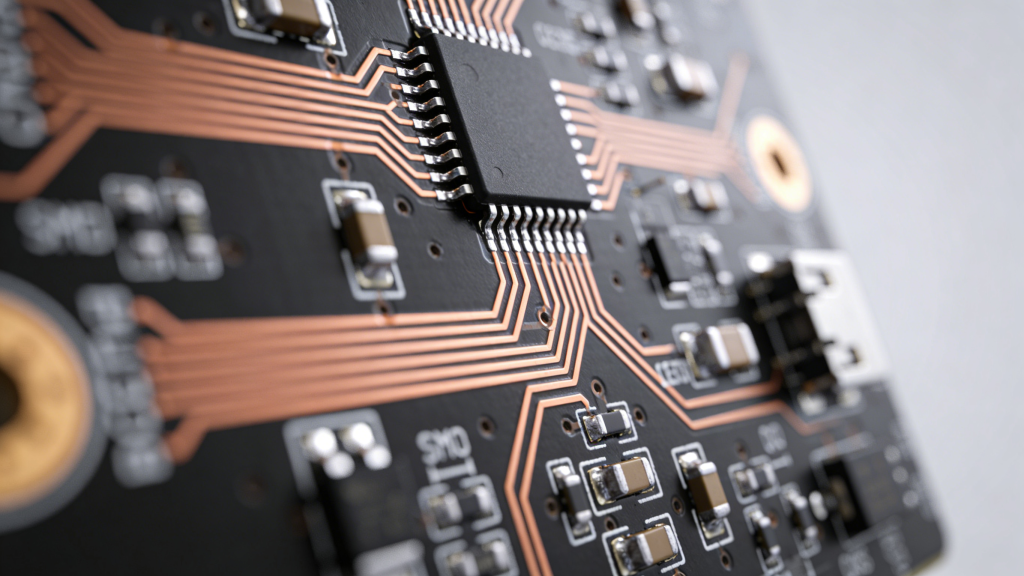
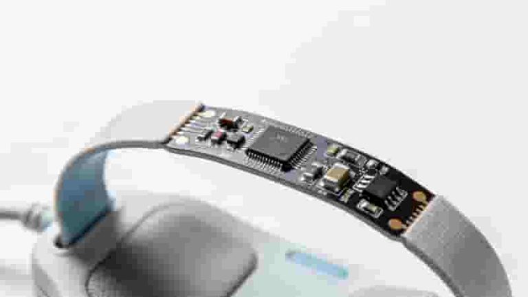
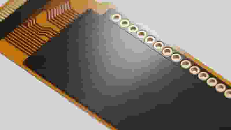
A flexible printed circuit (FPC) is a lightweight, bendable circuit built on flexible insulating substrates. It supports high-density assembly, three-dimensional wiring, and space-saving installation, widely used in consumer electronics, automotive, medical, and aerospace fields.
Unlike rigid PCBs, flexible circuit board materials determine flexibility, heat resistance, reliability, and cost. Choosing the right materials directly ensures product stability and long-term performance.
Core Flexible Circuit Board Materials
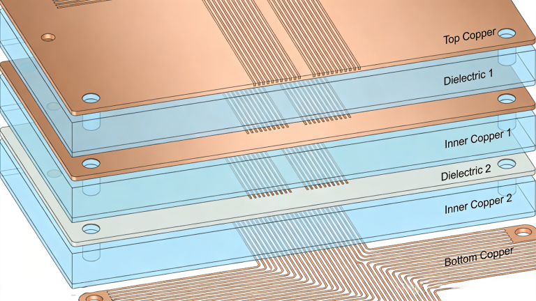
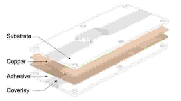
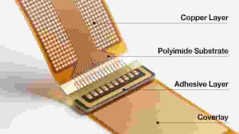
Standard flexible circuit board materials consist of five key components:
- Insulating substrate films (PI, PET, PTFE)
- Conductive copper foils (rolled, electrolytic)
- Adhesives for layer bonding
- Coverlay protective layers
- Stiffener reinforcing materials
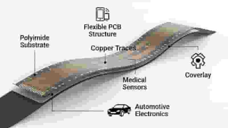
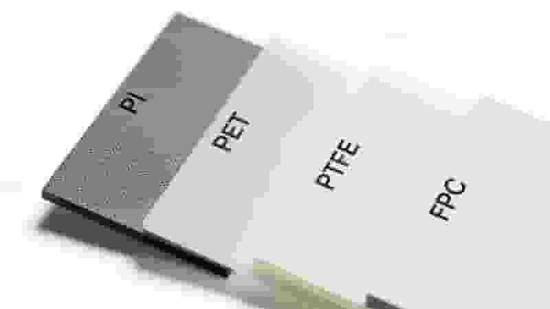
Insulating Substrate Films
Substrates are the foundation of flexible circuit board materials. They provide insulation, mechanical support, and thermal stability.
Polyimide (PI) Film
PI is the most widely used substrate in flexible printed circuits. It offers excellent heat resistance, solderability, and mechanical stability. Used in over 80% of industrial FPC products.
- Heat resistance: up to 260°C
- Common thickness: 12.5μm – 125μm
- Suitable for reflow soldering and high-reliability devices
Polyester (PET) Film
PET is a low-cost alternative for low-temperature applications. It has good flexibility and dimensional stability but cannot withstand soldering.
PTFE (Teflon) Film
PTFE provides ultra-low dielectric loss, extreme chemical resistance, and high thermal stability. Ideal for high-frequency, military, and aerospace flexible circuit board materials.
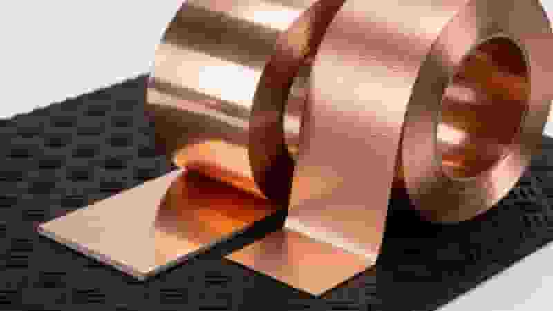
Conductive Copper Foils
Copper foil is the conductive core of all flexible circuit board materials. Two types dominate the industry:
Rolled Annealed Copper Foil
Superior ductility and bending life. Elongation 20–45%. Best for dynamic bending flexible printed circuits.
Electrodeposited Copper Foil
Lower cost, stable performance. Elongation 4–40%. Suitable for static bending applications.
Standard thicknesses: 0.5oz (18μm), 1oz (35μm), 2oz (70μm).
FPC Adhesives
Adhesives bond substrates, copper, and protective layers in flexible circuit board materials.
- Acrylic adhesive: high heat resistance, strong bonding
- Epoxy adhesive: balanced performance, good insulation
Coverlay & Protective Layers
Coverlay protects circuits from oxidation, moisture, and physical damage. It is a critical part of reliable flexible circuit board materials.
- PI Coverlay: high temperature resistance
- Liquid Photoimageable Solder Mask: for fine-pitch circuits
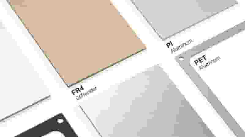
Stiffener Materials
Stiffeners reinforce connector and component areas. Common flexible circuit board materials for stiffening:
- FR4: high strength, low cost
- PI: high heat resistance
- PET: low cost, non-soldering
- Aluminum / Steel: heat dissipation + reinforcement
Material Performance Comparison
| Property | PI Film | PET Film | PTFE Film |
|---|---|---|---|
| Heat Resistance | Excellent | Fair | Excellent |
| Solderable | Yes | No | Yes |
| Cost | Medium | Low | High |
Flexible Circuit Board Materials Selection Guide
Select flexible circuit board materials based on working environment, bending frequency, temperature, and assembly process:
- Dynamic bending: choose rolled copper + PI
- Low-cost consumer goods: PET substrate + electrolytic copper
- High-frequency devices: PTFE materials
- Reflow soldering: PI + thermosetting adhesive
Conclusion
Understanding flexible circuit board materials helps you select the most reliable, cost-effective solution for your project. From substrates and copper foils to adhesives and stiffeners, each component directly impacts FPC performance, lifespan, and total cost.
We provide professional FPC design, material customization, and mass production support for global buyers. Contact us to get optimized solutions based on your application.
Get Your FPC Material & Quotation Support
Tell us your application, bending requirements, and quantity. We will provide professional material suggestions and a detailed quote.
Request FPC Quote Now
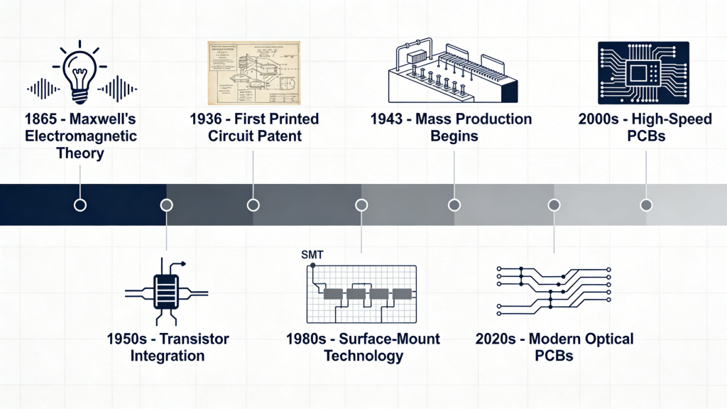
The Historical Timeline and Future Outlook of Printed Circuit Boards
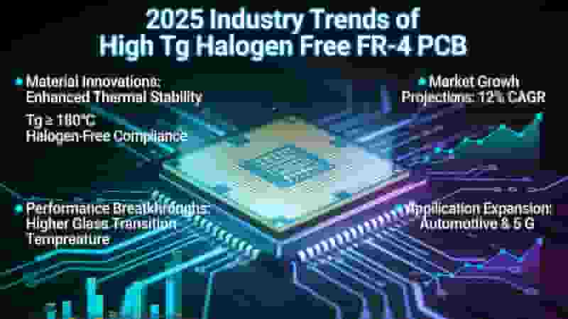
Why Choose FR-4 as Your PCB Material in 2025? The Definitive Engineer’s Guide
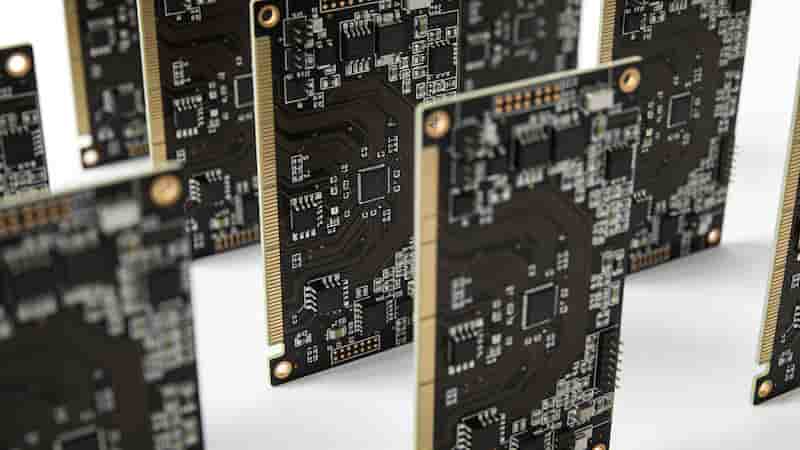
Rapid PCB Prototyping Services: A Comprehensive Introduction
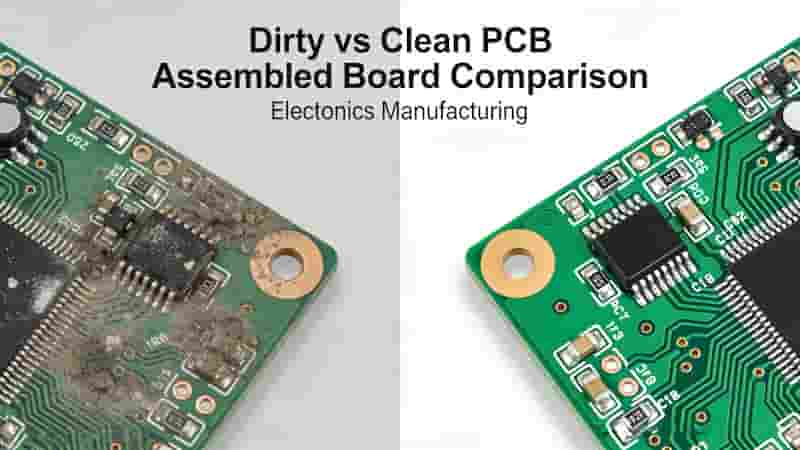
How to Effectively Clean PCB Assembled Boards for Optimal Performance
Flexible Circuit Board Surface Plating: Complete Technical Guide