Surface plating for flexible circuit boards is critical to solderability, oxidation resistance, bending reliability, and service life. This guide covers FPC basics, plating pretreatment, thickness control, stain prevention, electroless plating, hot air leveling, and best practices for engineers and buyers.
Flexible Circuit Board Basics
A flexible printed circuit board (FPC) uses a flexible insulating base material, enabling bending, folding, and dynamic installation. Rigid-flex PCB combines rigid PCB and flexible layers for high‑density, high‑reliability electronic devices.
Single‑sided FPC
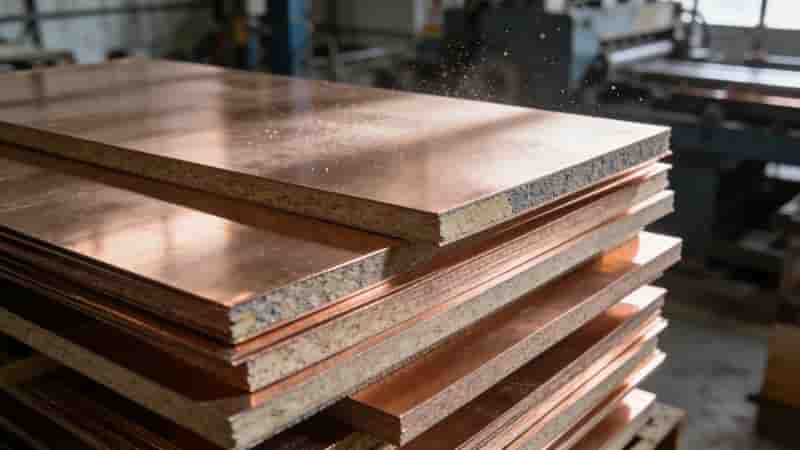
Single‑sided FPC has one conductor layer, with or without a cover layer. Common substrates: polyester, polyimide, PTFE, flexible epoxy glass cloth.
- No cover layer: lowest cost, for mild environments
- With cover layer: most widely used, for automotive & industrial instruments
- Double‑sided pads without cover layer: for dual‑side component mounting
- Double‑sided pads with cover layer: insulated, reliable for dynamic use
Double‑sided FPC
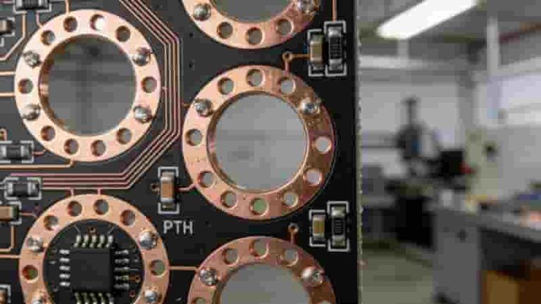
Double‑sided FPC has two conductor layers, improving wiring density. Types: with/without plated through holes, with/without cover layer.
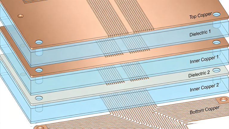
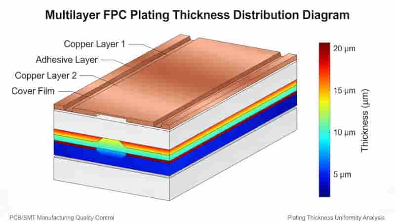
Multilayer FPC
Multilayer FPC uses lamination technology. 4‑layer is standard (power & ground inner layers). Lighter than rigid multilayer PCB with stable electrical performance.
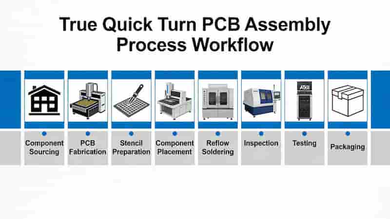
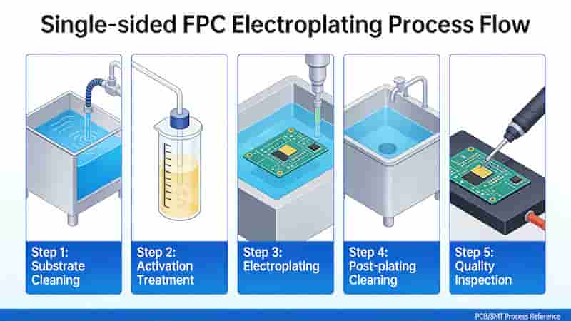
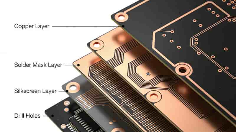
FPC Surface Plating Process
FPC plating ensures conductivity, solderability, and corrosion resistance. Key steps include pretreatment, thickness control, and cleaning.
Plating Pretreatment
Remove contaminants, adhesives, and oxides from copper surfaces. Improper treatment weakens cover layer adhesion and causes plating solution penetration.
Plating Thickness Control
Thickness depends on electric field intensity: fine lines and terminal edges deposit thicker metal. Uniformity ensures consistent performance.
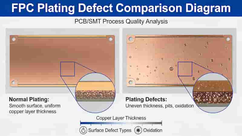
Stain & Discoloration Prevention
Residual chemicals cause post‑plating stains. Full rinsing and drying prevent discoloration. Thermal aging testing verifies cleaning quality.
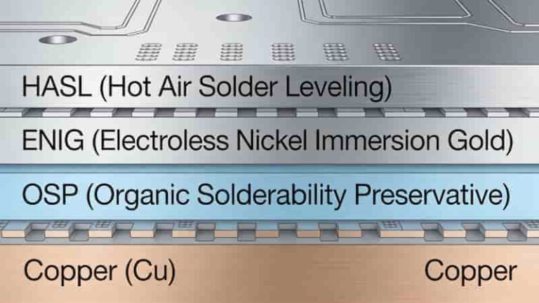
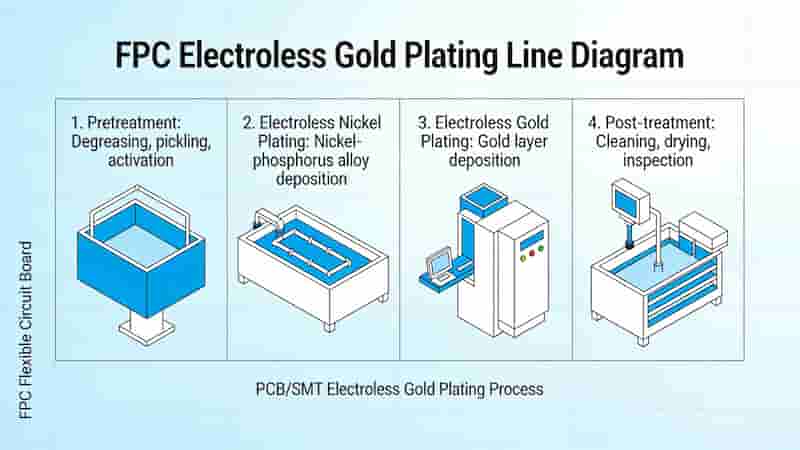
Electroless Plating for FPC
Used when conductors cannot be electrified. Typical process: electroless gold plating. High pH solutions may penetrate under cover layers; strong lamination bonding is required.
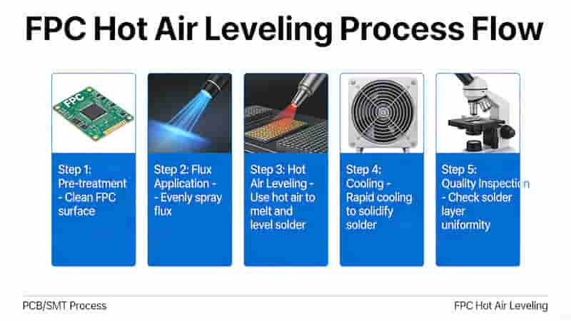
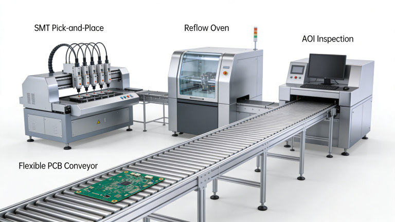
FPC Hot Air Leveling (HASL)
HASL applies molten solder then blows excess with hot air. FPC requires fixturing to avoid warping. Pre‑baking removes moisture to prevent bubbling or delamination.
| Item | Electroplating | Electroless Plating | HASL |
|---|---|---|---|
| Suitability | General FPC | Isolated Lines | Stable FPC |
| Risk | Low | Medium | High (Delamination) |
| Cost | Medium | High | Low |
Summary & Best Practices
Flexible circuit board surface plating directly affects reliability. Strict pretreatment, uniform thickness, full cleaning, and proper fixturing ensure high‑quality results. Choose plating type based on application, environment, and bending requirements.
Custom Plating Service Inquiry
We provide professional flexible PCB surface plating and manufacturing services for global buyers. Get free quotation, technical support, and customized solutions for your FPC projects.
Contact us with your Gerber files, layer count, material, thickness, and quantity for a fast and accurate quote.
Request FPC Plating Quote
PCB & PCBA Manufacturing Files: Complete Guide for Production & Quotation
PCB Manufacturing Process Part 1: MI, Cutting & Drilling – Complete Industrial Guide
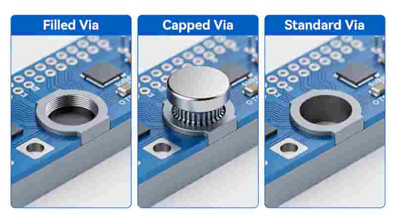
Filled and Capped Vias: Boost PCB Reliability for Industrial & Export Applications
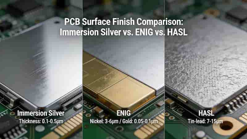
Immersion Silver PCB Surface Finish: Benefits, Applications, Cost Analysis & IPC Standards
Blind Vias & Buried Vias in PCBs – The Complete Technical Guide