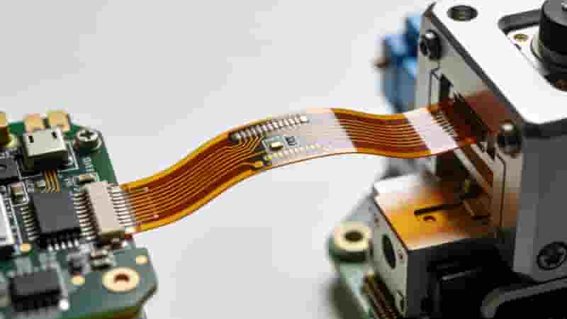
Flexible PCB (FPC/flex circuit) is a thin, bendable printed circuit that fits 3D spaces. This engineering guide covers materials, design rules, manufacturing, types, reliability & industrial uses for global buyers.
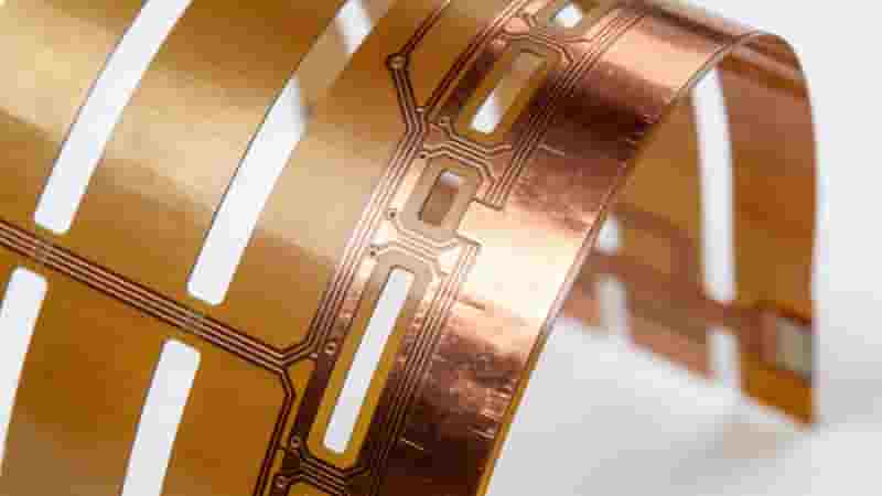
Modern electronics demand thinner, lighter, higher-density interconnects. Flexible PCB (also called FPC or flex circuit) has become a core technology enabling miniaturization and 3D packaging. Unlike rigid FR-4 boards, flex circuits bend, fold and twist to fit complex mechanical structures while maintaining stable electrical performance.
A flexible PCB uses flexible polymer films as substrates instead of rigid glass epoxy. It reduces weight, volume, connectors and failure points, widely used in consumer electronics, medical, automotive, aerospace and industrial equipment.
What Is a Flexible PCB?
A flexible PCB is a printed circuit board built on bendable insulating substrates. It supports repeated bending, folding and twisting while retaining electrical function. It routes power and signals like standard PCBs but offers unmatched mechanical flexibility for compact, dynamic designs.
Traditional rigid PCBs stay flat; flexible PCB conforms to curved surfaces, passes through narrow hinges and wraps around mechanical parts. It replaces multiple rigid boards, cables and connectors with one integrated assembly, improving reliability and reducing assembly time.
Structure & Types of Flexible PCBs
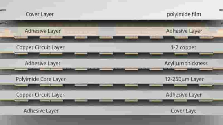
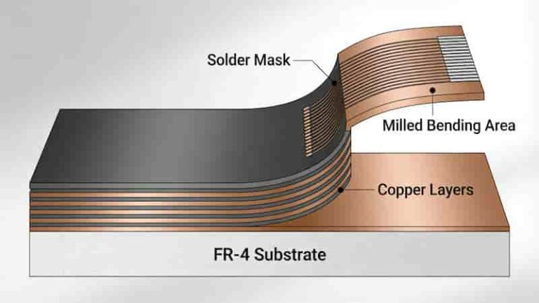
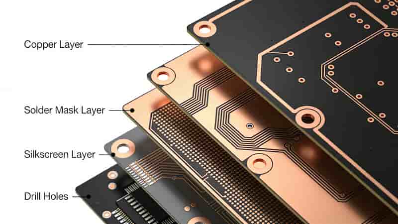
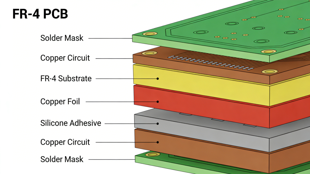
A standard flex circuit includes substrate film, copper foil, adhesive layers and coverlay. Below are the four most common types.
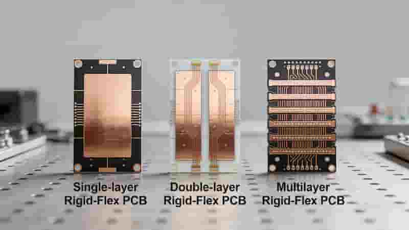
1. Single‑sided Flexible PCB
One copper layer on polyimide film, with one coverlay layer. Low cost, high flexibility, ideal for simple circuits and high-volume consumer products.
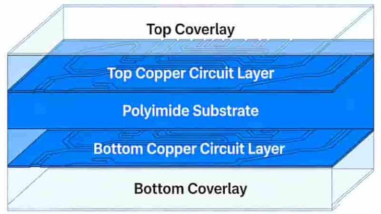
2. Double‑sided Flexible PCB
Copper on both sides, connected by plated vias. Higher routing density, suitable for cameras, automotive sub-assemblies and medical devices.
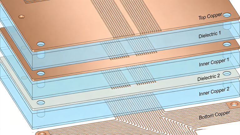
3. Multilayer Flexible PCB
Three+ copper layers with flexible dielectrics. Supports high-density circuits, controlled impedance and shielding for aerospace, medical and high-speed electronics.
4. Rigid‑Flex PCB
Combines rigid and flex sections in one assembly. Eliminates cables/connectors, widely used in smartphones, aerospace, military and medical implants.
Key Materials for Flexible PCB
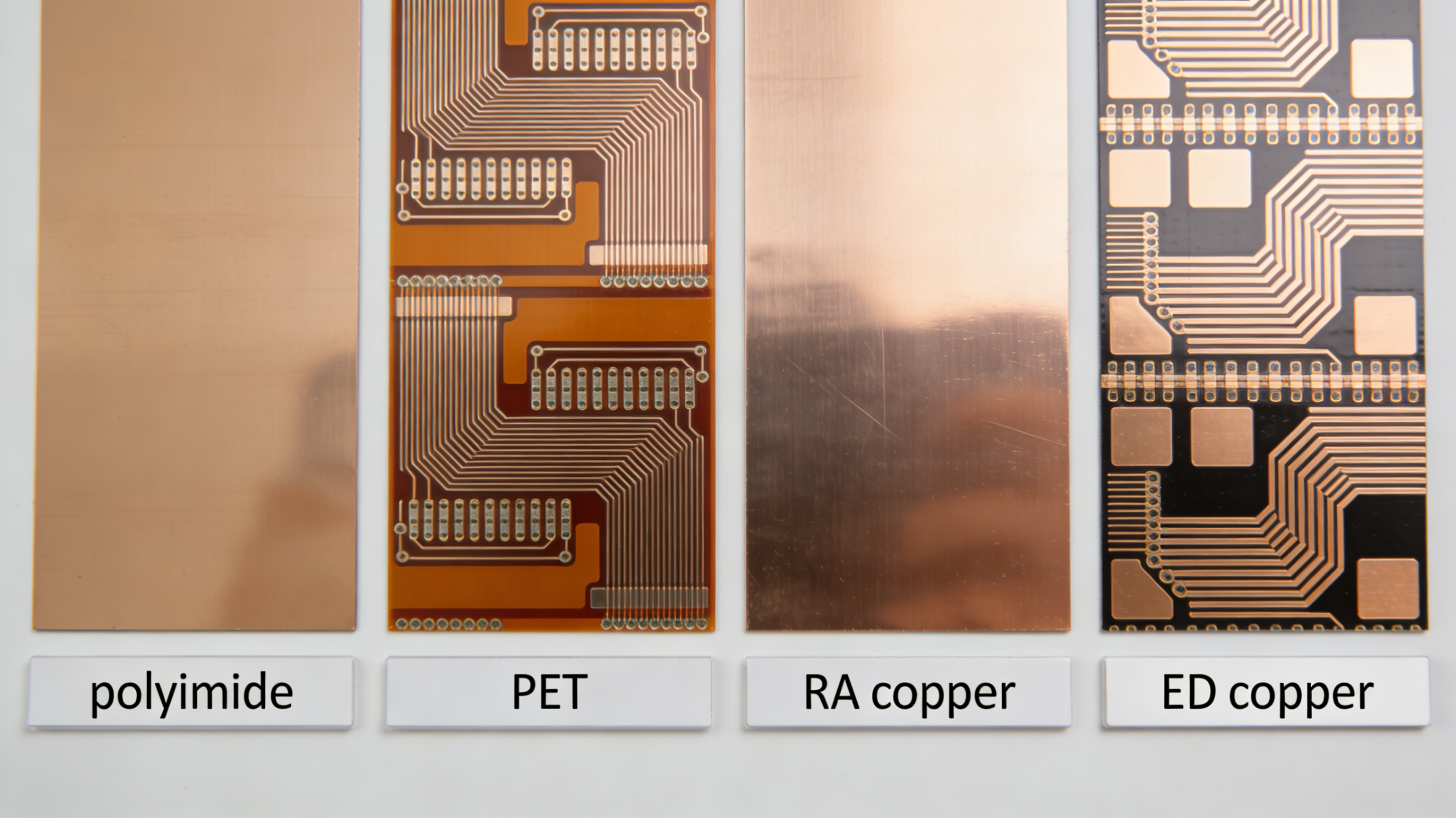
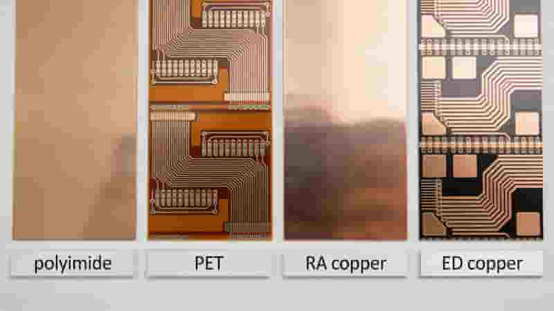
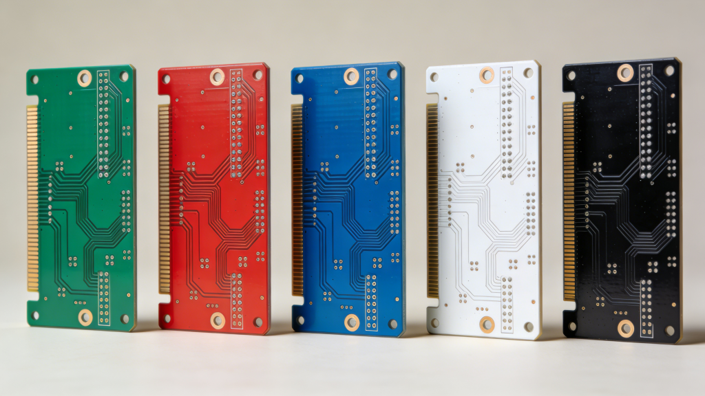
Base Films
Polyimide (PI): High temperature resistance (−200℃ to 260℃), long flex life, used in high-reliability applications.
PET: Lower cost, for static or low-flex consumer products.
Copper Foil
RA Copper: High ductility, ideal for dynamic bending (millions of cycles).
ED Copper: Lower cost, for static or low-cycle flex uses.
Other Critical Materials
Coverlay (protective insulation), stiffeners (FR‑4/PI/steel for component mounting), adhesives or adhesiveless laminates.
Benefits & Limitations of Flexible PCB
Core Benefits: 3D flexibility, lightweight, thin profile, fewer connectors, higher reliability under vibration, better heat dissipation, simplified assembly.
Limitations: Higher unit cost than rigid PCB, sensitive to handling, design constraints in bend zones.
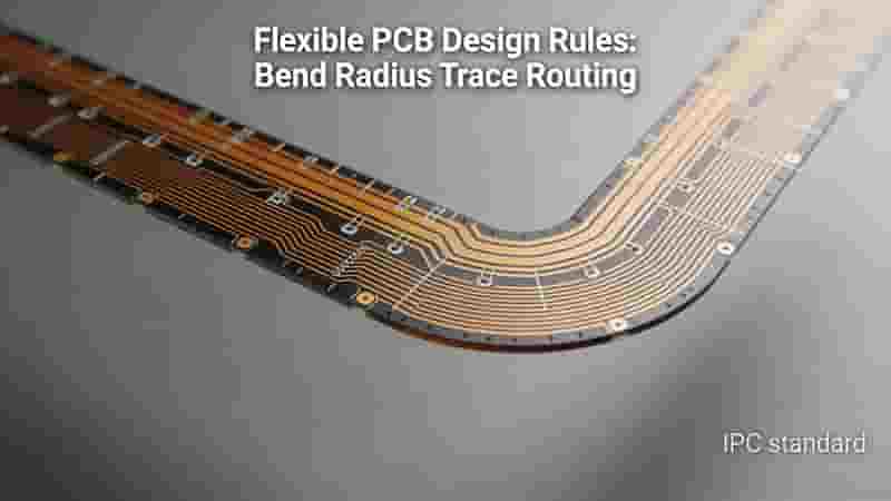
Flexible PCB Design Guidelines (IPC‑2223)
- Minimum bend radius: static ≥10× thickness; dynamic ≥20× thickness
- Use curved traces, avoid 90° corners to reduce stress
- Keep vias out of active bending zones
- Add stiffeners under components and connectors
- Use RA copper for dynamic flex applications
- Maintain balanced copper distribution in flex areas
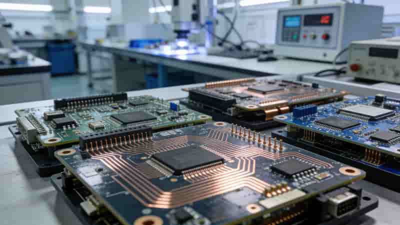
Flexible PCB Manufacturing Process
- Laminate cutting & preparation
- Drilling & via metallization
- Circuit patterning & etching
- Coverlay lamination
- Surface finishing (ENIG, immersion tin, etc.)
- Profile cutting & electrical testing
- Assembly with SMT fixturing
Industrial Applications of Flexible PCB
Consumer Electronics: Smartphones, wearables, cameras, foldable devices
Medical: Implants, diagnostic tools, wearable monitors
Automotive & EV: Sensors, ADAS, infotainment, battery systems
Aerospace & Industrial: Avionics, robotics, dynamic control modules
When to Choose Flex/Rigid-Flex vs Rigid PCB
| Feature | Flexible PCB | Rigid PCB (FR‑4) |
|---|---|---|
| Flexibility | Bendable, foldable, 3D conformable | Non‑bendable |
| Weight & Thickness | Ultra‑thin, lightweight | Thicker, heavier |
| Dynamic Use | High vibration & flex endurance | For static environments |
| Typical Cost | Higher | Lower |
Failure Modes & Reliability Improvement
Common failures: trace cracking, delamination, pad lift, via fatigue in bending zones.
Solutions: follow IPC standards, use proper bend radius, select RA copper, avoid vias in flex zones, add stiffeners, use high‑bonding coverlay.
Conclusion
Flexible PCB is an essential interconnect solution for modern compact, high‑reliability electronics. With the right materials, design and manufacturing, flex circuits deliver superior performance in 3D spaces, dynamic motion and weight‑critical applications.
Whether you need prototypes, mass production or custom rigid‑flex solutions, we provide full DFM review, reliable quality and global delivery for industrial buyers worldwide.
Need Custom Flexible PCB Solutions?
Send Gerber, BOM & specs for a free, fast quote. We support global export with IPC standards, fast lead times and 100% quality control.
Request a Quote
Contact Engineering Team
PCB & PCBA Manufacturing Files: Complete Guide for Production & Quotation
High Tg PCB Materials: A Comprehensive Guide to High-Temperature Performance and Applications
PCB Solder Mask: The Complete Technical Guide for Global Buyers

Navigating The PCB Manufacturing Process Part 2: Copper Plating, Routing
What is FR-4 Material in PCB Fabrication? Complete Engineering Guide