|

Aluminum PCB Prototype: The Ultimate Guide for Engineers and Designers

Bare Aluminum PCB Prototype Fabrication Sample

This complete engineering guide covers Aluminum PCB Prototype basics, thermal advantages, material selection, fabrication process, assembly, applications, and how to select a reliable supplier for high‑performance electronics projects.
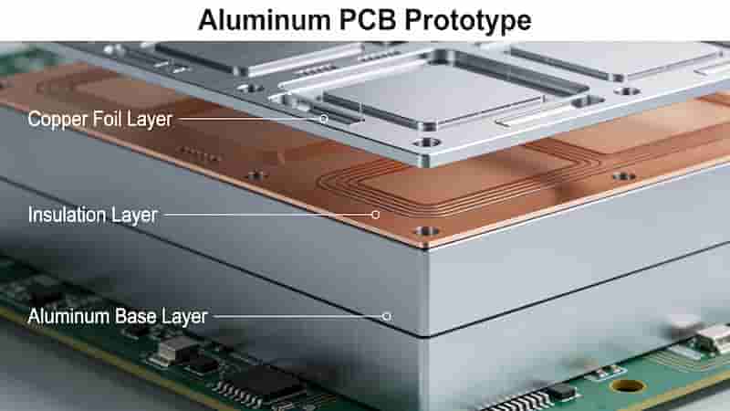
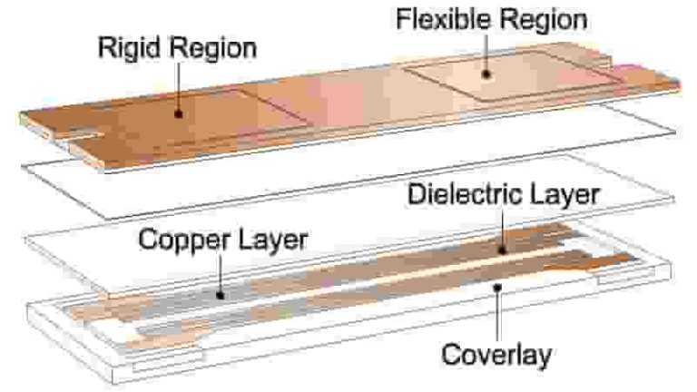
Aluminum PCB Prototype Blank Board Thermal Management Structure

What Is an Aluminum PCB Prototype?

An Aluminum PCB Prototype is a metal‑core printed circuit board that uses aluminum alloy as its base material substrate instead of standard FR4. It delivers exceptional thermal conductivity and structural stability, making it the first choice for high‑power, high‑heat electronic designs.

Unlike FR4 PCBs, Aluminum PCB Prototype boards quickly transfer heat away from components, greatly improving reliability and lifespan in demanding environments.

Key Advantages of Aluminum PCB Prototypes

1. Superior Thermal Performance
Aluminum provides far higher thermal conductivity than FR4. A Aluminum PCB Prototype efficiently dissipates heat, lowers operating temperatures, and extends component life.

2. Improved Electrical Stability
Stable dielectric properties reduce signal loss and crosstalk. Aluminum PCB Prototype designs support better signal integrity and power efficiency.

3. Lighter Weight & Higher Strength
Aluminum offers excellent mechanical strength while being lighter than many metal alternatives, ideal for automotive and aerospace use.

4. Durability & Environmental Resistance
Great corrosion resistance and durability make Aluminum PCB Prototype boards suitable for outdoor, industrial, and harsh environments.
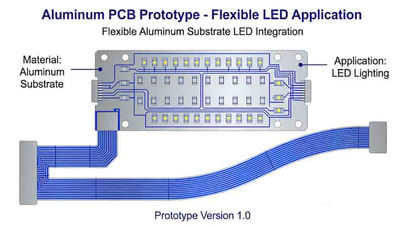
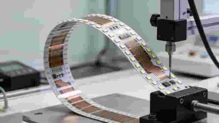
Flexible Aluminum PCB Board for LED and Power Devices

Typical Applications of Aluminum PCB Prototypes

An Aluminum PCB Prototype is widely used in industries that require high thermal management:

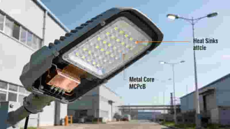
  • High‑Power LED Lighting
  • Power Supplies, Inverters, and Converters
  • Automotive Electronics Control Units
  • Aerospace and Avionics Systems
  • Medical Imaging and Surgical Equipment
  • Industrial Control and Power Drivers
Bare Aluminum PCB Prototype Fabrication Sample

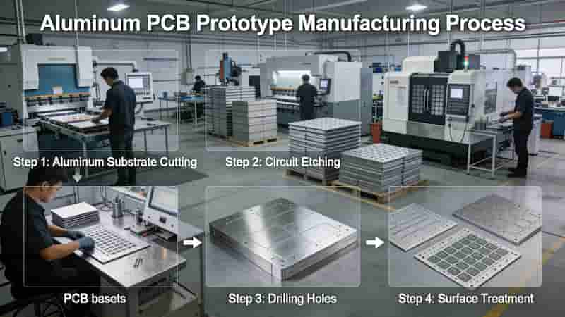
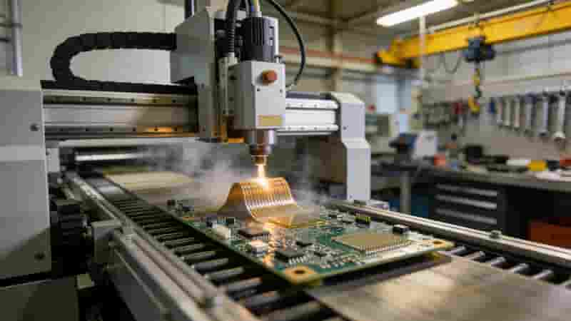
Aluminum PCB Prototype Fabrication Process

The production of a Aluminum PCB Prototype follows precise steps to ensure heat dissipation and reliability:

1. Material Selection
Common alloys: 5052, 6061. Thickness and thermal conductivity are selected based on design needs.

2. Surface Treatment & Bonding
Aluminum surface is cleaned and insulated to support copper foil lamination.

3. Circuit Patterning & Etching
Copper layers are imaged and etched to form circuit traces.

4. Drilling & Plating
Holes are drilled and plated for electrical connection and isolation.

5. Surface Finish & Testing
Common finishes: HASL, immersion gold, tin. Final electrical and thermal tests ensure quality.
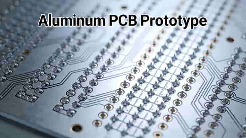
Aluminum PCB Fabrication and Prototype Production Line

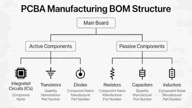
Aluminum PCB Prototype Assembly

Assembly of a Aluminum PCB Prototype requires special thermal profile settings due to metal substrate characteristics:

  • Component selection for high‑heat compatibility
  • Solder paste printing with optimized stencil design
  • Reflow soldering with controlled temperature zones
  • AOI visual and electrical inspection
  • Functional testing for performance validation

How to Choose a Reliable Aluminum PCB Prototype Manufacturer

Selecting the right partner ensures your Aluminum PCB Prototype meets performance, cost, and lead time goals:

1. Experience & Technical Capability
Focus on manufacturers with proven expertise in metal‑core PCB and thermal design.

2. Quality & Testing System
Check for IPC standards, material certifications, and in‑house testing capabilities.

3. Lead Time & Pricing
Compare quick‑turn prototype services and transparent cost structures.

4. Customer Support & DFM Service
Strong engineering support helps optimize your Aluminum PCB Prototype design for mass production.
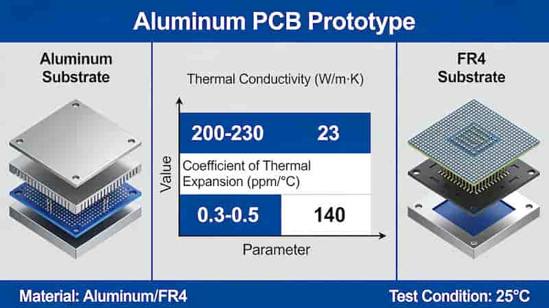
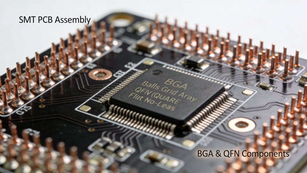
Aluminum PCB Prototype SMT Assembly and Testing Process

Conclusion

A Aluminum PCB Prototype provides superior thermal performance, reliability, and durability compared to FR4 prototypes. It is essential for high‑power LED, automotive, industrial, and aerospace designs.

By understanding materials, fabrication, assembly, and supplier selection, engineers and designers can confidently use Aluminum PCB Prototype solutions to improve product performance and accelerate time to market.

Get Your Aluminum PCB Prototype Solution

Contact us for free DFM analysis, quick quotes, custom prototypes, and reliable mass production support.

Request a Quote Now
High Tg PCB manufacturing process and production line

High Tg PCB Manufacturing for High Temperature Applications

Posted on
0 Comments
We manufacture reliable High Tg PCB boards using Tg 170–180+ FR‑4 materials, engineered for automotive, power electronics, industrial control, and telecom applications that must survive elevated temperatures and demanding duty cycles. What Is a High Tg PCB A High Tg PCB is a printed circuit board made with materials that have a higher glass transition…
Copper Core PCB Structure - High Thermal Conductivity Copper Base

Copper Core PCB vs. Metal Core PCB: Key Differences & Advantages

Posted on
0 Comments
Copper Core PCB delivers superior thermal conductivity and stability for high-power electronics, while Metal Core PCB offers cost-effective thermal management for general industrial and commercial applications. Introduction to PCB Technology Printed Circuit Boards (PCBs) are the foundational building blocks of modern electronic devices. From consumer electronics to industrial machinery, PCBs ensure reliable electrical connectivity and…
Step Stencil vs Standard Stencil Comparison PCB SMT Production

Step Stencils: Precision Solutions for Modern PCB Assembly

Posted on
0 Comments
Step stencils optimize solder paste deposition for mixed-component PCBs, improving yield, reliability, and first-pass success in SMT assembly for electronics, automotive, and medical devices. Imagine a production line where tiny 01005 components sit alongside large edge connectors on a single printed circuit board. The challenge? Applying just the right amount of solder paste to each…
Plated Half-Hole PCB Overview Castellated Holes

Understanding Plated Half-Holes (Castellated Holes) in PCB Design

Posted on
0 Comments
Plated half-holes (also known as castellated holes) offer a space-efficient, reliable method for interconnecting PCB modules through direct soldering. Positioned at board edges, they simplify assembly, improve alignment, and boost mechanical stability compared to traditional bottom pads. This guide covers structure, design rules, fabrication, benefits, applications, and best practices for engineers and buyers. What Are…
Rigid Flexible PCB Basic Structure Diagram

Rigid-Flex PCB Stackup: Design and Manufacturing Guide

Posted on
0 Comments
Rigid-flex PCB stackup combines rigid and flexible layers for compact, reliable designs. Explore its types, design tips, and applications in this professional guide. Introduction to Rigid-Flex PCB Rigid-flex PCBs combine the strengths of rigid and flexible circuits, creating a hybrid solution for complex, high-density electronic designs. Integrated by plated through holes (PTH), these boards support…
Single-Sided Flex PCB Bending Radius Static vs Dynamic IPC Standard

Single-Sided Flexible PCB Design Guide: Bending Radius, Trace Routing and Stiffeners

Posted on
0 Comments
Single-sided flexible PCBs look simple, but poor design on bending radius, trace layout or stiffener placement can quickly lead to cracks and failures. This engineering guide provides practical rules for minimum bend radius, trace routing in flex zones, and stiffener usage to keep single-sided flexible PCB reliable in static and dynamic applications. Introduction to Single-Sided…

FAQs About Aluminum MCPCB Prototype Spec, Process & Supplier Selection

A: Aluminum PCB uses aluminum alloy as base substrate; outstanding thermal dissipation far above FR4, specially customized for high-power high-heat prototype development.

A: Excellent heat conduction, stable electrical signal performance, lightweight plus high mechanical rigidity and good anti-corrosion for harsh working conditions.

A: 5052 and 6061 aluminum alloy are mainstream base materials selected per thermal dissipation requirement and mechanical design demand.

A: Aluminum base pretreatment → insulating dielectric bonding → copper lamination & circuit etching → drilling/plating → surface finish → electrical & thermal performance testing.

A: Aluminum base fast heat absorption and conduction, must adjust oven temperature curve to avoid cold solder or overheating damage during component soldering.

A: High-power LED driver, switching power supply, automotive power control module, industrial inverter and medical high-power imaging equipment.

A: Rich MCPCB processing experience, full IPC-compliant QC test system, fast-turn prototype lead time and free professional DFM optimization service.

A: HASL, immersion tin and immersion gold; selected based on storage cycle, soldering requirement and overall project cost budget.

Similar Posts