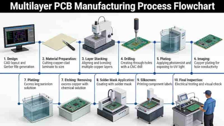
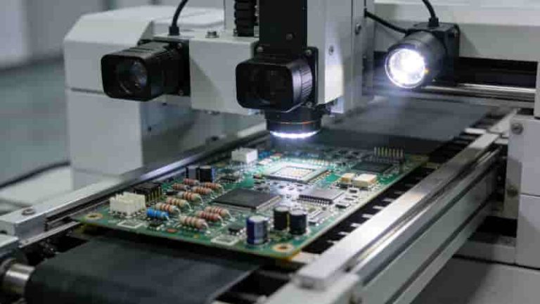
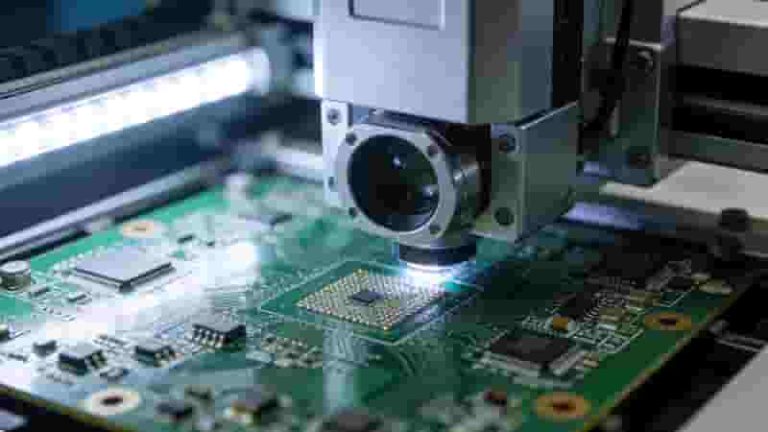
|

How to Choose a Reliable PCB Prototype Manufacturer for Electronics Projects

PCB DFM Analysis Engineering Support SMT Assembly

Selecting a trusted PCB prototype manufacturer directly impacts product performance, development speed, and long-term reliability. This professional guide helps engineers and buyers evaluate technical capabilities, quality systems, lead times, and services to pick the ideal partner for your electronic projects.

Technical & Manufacturing Capabilities

A professional PCB prototype manufacturer must match your design complexity and application requirements.

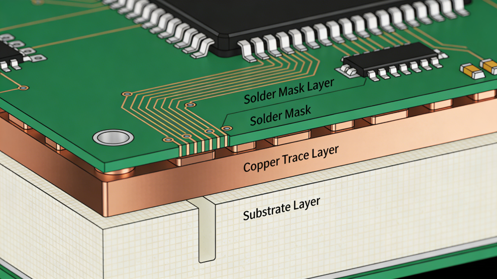
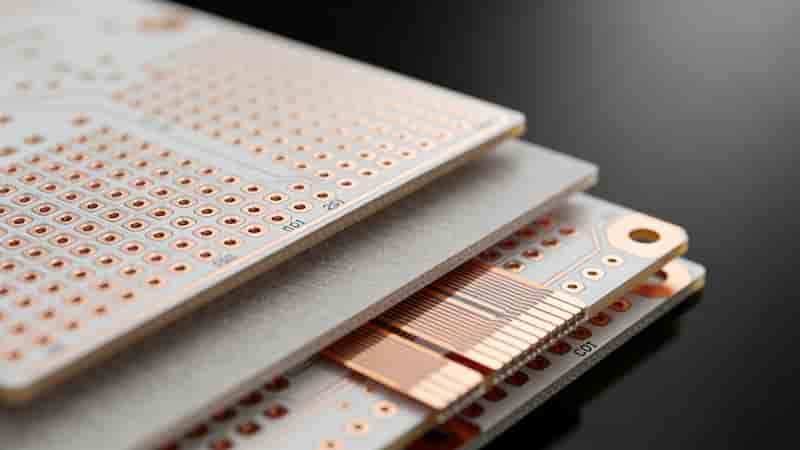
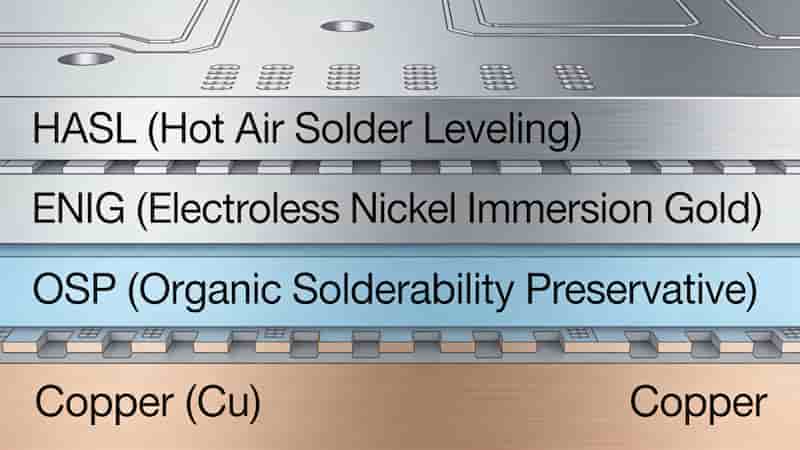
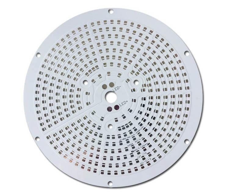
Key capabilities include layer count (1–40+ layers), minimum trace/space, hole size, HDI, rigid‑flex, high‑frequency, and metal core boards. Supported materials include FR‑4, Rogers, Isola, aluminum, and polyimide. Surface finishes cover HASL, ENIG, OSP, immersion tin, and hard gold.

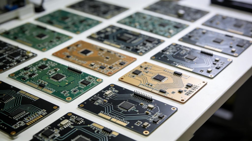
PCB Prototype Technical Capabilities Layers HDI Materials

We support fine pitch down to 3/3 mil, microvias, impedance control, and specialized processing for aerospace, medical, automotive, and 5G applications.

Quality Assurance & Certifications

Reliable quality systems separate professional PCB prototype manufacturers from standard suppliers.

Essential certifications: ISO 9001, UL, RoHS, IPC-A-600, IPC Class 2/3. In-line testing includes AOI, flying probe, X-ray for BGA, electrical continuity, and thermal stress tests.
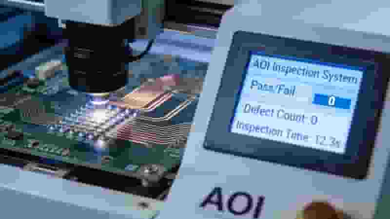
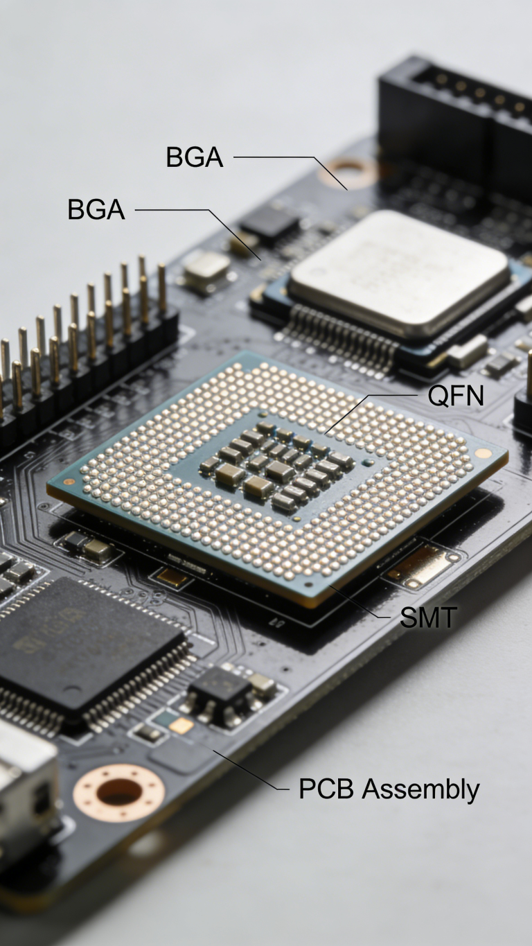
PCB Quality Control AOI X-Ray Testing

Full material traceability and strict incoming inspection ensure every PCB prototype meets design specifications and industry standards.

Lead Time & Scalability

Fast, stable delivery is critical for R&D cycles. Top PCB prototype manufacturers offer flexible turnaround options.

Standard: 3–5 days; Expedited: 24–48 hours for simple boards. Seamless scaling from prototypes to mid‑volume production reduces switching costs and shortens time‑to‑market.

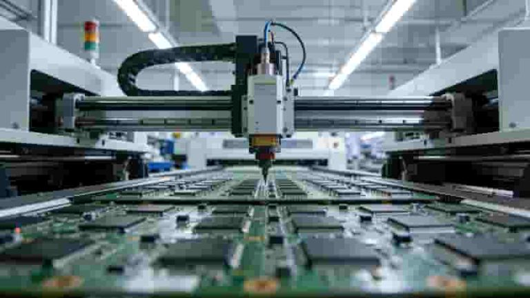
PCB Prototype Lead Time Fast Turnaround Production

We maintain stable material inventory and efficient production lines to honor committed lead times for your PCB prototype projects.

Engineering Support & Value‑Added Services

Professional support reduces risks and lowers total costs. A qualified PCB prototype manufacturer provides:

  • Free DFM analysis to optimize design
  • Engineer‑to‑engineer technical support
  • One‑stop PCB + SMT assembly
  • NDA protection for confidential designs
  • Transparent pricing with no hidden fees
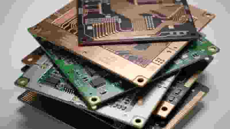
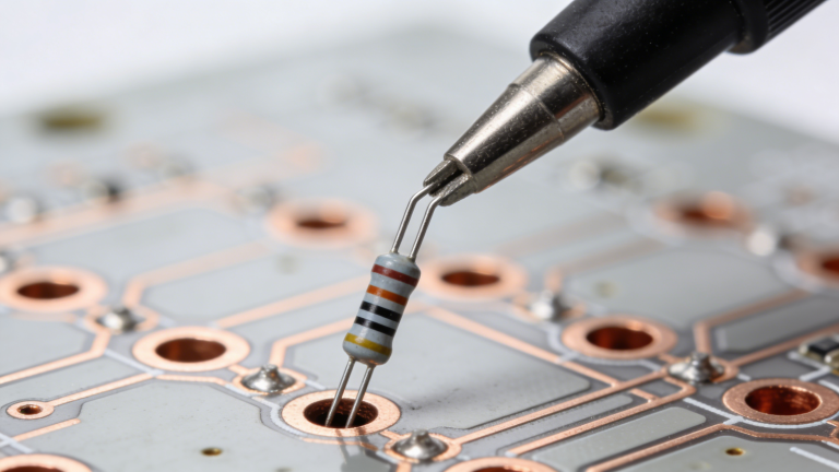
PCB DFM Analysis Engineering Support SMT Assembly

PCB Prototype Manufacturer Evaluation Comparison

ItemStandard SupplierProfessional PCB Prototype Manufacturer
CertificationsBasic onlyISO 9001, UL, RoHS, IPC
TestingBasic visualAOI, X‑ray, flying probe
DFM SupportLimited or noneFree full analysis
Lead TimeUnstable24h–5d guaranteed

Conclusion

Choosing the right PCB prototype manufacturer is a strategic decision affecting performance, cost, and launch speed. Prioritize technical capability, certified quality, reliable lead times, and professional engineering support.

We specialize in high‑reliability PCB prototypes for industrial, medical, automotive, and IoT applications, with full technical support and global export service.

Need a Reliable PCB Prototype Partner?

Send your Gerber files for a free DFM check and quick quote. We support fast-turn prototypes and global delivery for your electronics projects.

Request a Fre Quote
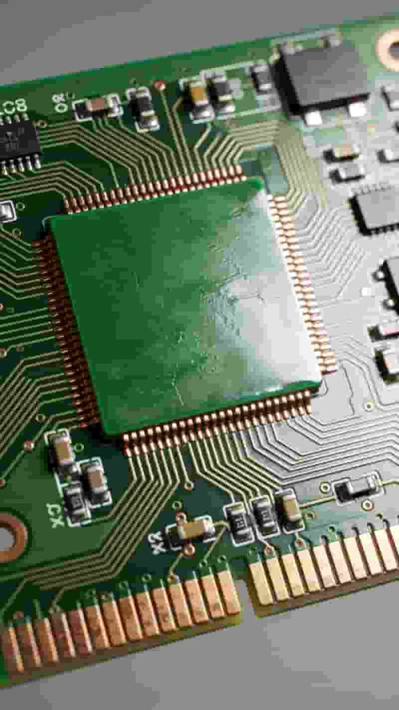
4 Types of PCB Open Circuit Diagram Repeated Gap Vacuum Scratched

PCB Open Circuit: Causes, Types, Diagnosis & Proven Solutions

Posted on
0 Comments
PCB open circuit is one of the most frequent defects in PCB manufacturing, causing production downtime, rework, delivery delays, and quality complaints. This professional guide explains definitions, types, root causes, inspection methods, prevention, and reliable fixes for global electronics buyers and engineers. What Is a PCB Open Circuit? A PCB open circuit is an interruption…
Flexible PCB basic structure polyimide copper coverlay layers

Flexible PCB: Complete Materials, Design & Industrial Application Guide

Posted on
0 Comments
A flexible PCB (FPC) is a thin, bendable printed circuit that can fold, twist, and fit compact 3D spaces. This guide covers structure, materials, stack‑ups, design rules, manufacturing, and real‑world use cases to help global engineers and buyers select the right flex solution. Introduction In every new generation of electronic products, there is a clear…
FR-4 PCB 2025 trends high Tg halogen free multilayer

Why Choose FR-4 as Your PCB Material in 2025? The Definitive Engineer’s Guide

Posted on
0 Comments
FR-4 remains the most trusted, cost-effective, and versatile PCB substrate for global industrial, automotive, consumer, and medical electronics. This guide explains key electrical, mechanical, thermal, and economic reasons to select FR-4 PCB for your 2025 projects. What is FR-4 PCB Material? FR-4 (Flame Retardant 4) is a fiberglass-reinforced epoxy laminate, the global standard for printed…
Flexible PCB Overview Structure and Applications

Flexible PCB Manufacturing Process Steps: Complete Technical Guide

Posted on
0 Comments
This professional guide covers full flexible PCB manufacturing workflow, materials, key processes, quality control, and engineering best practices for global industrial buyers, engineers, and procurement teams. What is Flexible PCB (FPC) Flexible PCB (FPC) is a lightweight, bendable printed circuit board widely used in consumer electronics, automotive, medical devices, and industrial equipment. It supports component…
PCB basic structure diagram showing trace pad silkscreen component

PCB Terminology Glossary – Over 150 Essential PCB Terms for Engineers & Global Buyers

Posted on
0 Comments
This professional PCB glossary provides clear, industry-standard definitions for over 150 key terms used in PCB design, manufacturing, assembly, and quality control. Ideal for engineers, procurement teams, and global buyers, this resource helps streamline communication, avoid misunderstandings, and ensure accurate project execution. We continuously update this list to cover the latest technologies and standards in…
PCB Manufacturability Analysis Software Interface DFA Check

Design for Manufacturability and Assemblability of Printed Circuit Board

Posted on
0 Comments
Optimize your PCB design for high yield, low cost, and reliable assembly with industry-leading DFM and DFA principles aligned with IPC standards. What is Design for Manufacturing Design for Manufacturing, also known as concurrent or simultaneous engineering, focuses on the relationship between product physical design and manufacturing systems. By integrating DFM principles into product design,…

FAQs About How to Select Qualified PCB Prototype Manufacturer

A: Max layer count, min line width/spacing, HDI/microvia/impedance control, available substrate types and full range of surface finish options.

A: ISO9001, UL, RoHS, IPC-A-600 qualification, capable of IPC Class2/3 high-reliability production for auto/medical/aerospace.

A: AOI automatic optical inspection, flying probe tester, X-ray for BGA inner layer check, electrical continuity tester and thermal stress test facility.

A: Expedited 24~48h for simple PCB; standard 3~5 working days, support smooth conversion from prototype to mass production later.

A: Free DFM design review, one-stop PCB+SMT turnkey assembly, NDA confidential protection and transparent all-in pricing without hidden cost.

A: Standard supplier lacks complete certification & full testing; professional factory owns full qualification, strict QC system and free DFM optimization support.

A: Medical implant equipment, automotive safety electronic module, aerospace control circuit and mission-critical industrial control products.

A: Submit Gerber files for free DFM checking and sample prototype production to verify lead time, workmanship and quality stability formally.

Similar Posts