Discover the best PCB material for your prototyping needs with our complete engineering guide. From FR‑4 to metal core, Rogers, polyimide, and ceramic PCBs, we help you select the ideal substrate for performance, cost, and reliability.
Introduction
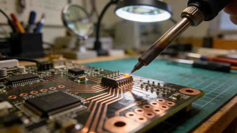
Selecting the right PCB material is crucial for ensuring your prototype delivers optimal performance, durability, and cost-efficiency. With materials like FR-4, metal core PCBs, Rogers PCBs, polyimide, and ceramic PCBs available, understanding their properties empowers you to make informed decisions. This comprehensive guide explores the advantages, disadvantages, and ideal applications of these materials, providing insights to streamline your PCB prototyping process. Whether designing for high-frequency, high-power, flexible, or extreme environments.
Why PCB Material Selection Matters
Your choice of PCB material directly impacts electrical performance, heat management, flexibility, reliability, and total cost. Proper selection helps you:
- Boost signal integrity for high‑frequency designs
- Improve heat dissipation for high‑power circuits
- Enable flexibility for compact or wearable devices
- Ensure stability in extreme temperatures and environments
- Optimize cost without reducing quality
We provide professional guidance to match the best PCB material to your project requirements.
Common PCB Materials and Their Properties
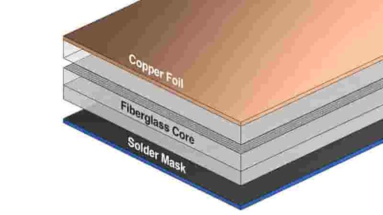
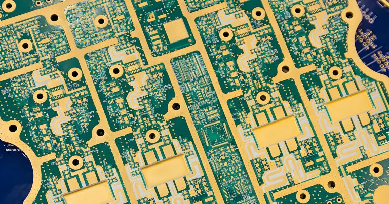
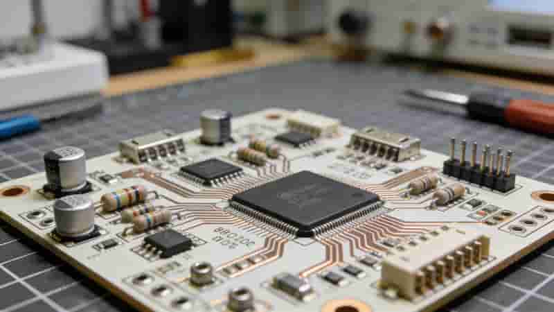
1. FR‑4 PCB
FR‑4 is the most widely used PCB material for rigid prototypes, balancing cost, insulation, and strength.
Advantages: Low cost, good electrical insulation, strong mechanical stability, widely supported.
Disadvantages: Limited thermal performance, not flexible.
Best for: Consumer electronics, general prototyping, low‑to‑medium power circuits.
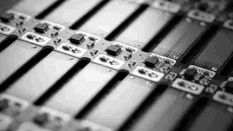
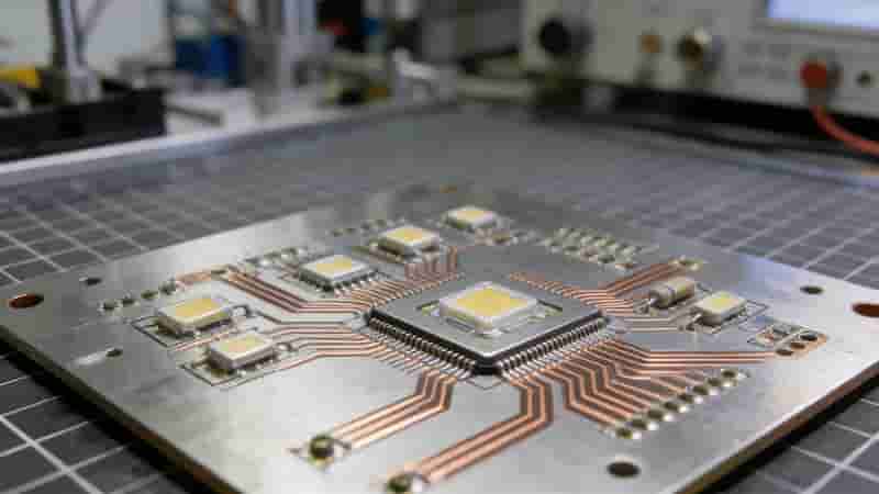
2. Metal Core PCB (MCPCB)
Metal core PCBs use aluminum or copper bases for excellent thermal management in high‑power designs.
Advantages: Superior heat dissipation, durable, thermally stable.
Disadvantages: Higher cost, rigid only.
Best for: LED lighting, power supplies, automotive electronics.
3. Rogers PCB
Rogers PCB material delivers premium performance for RF, microwave, and high‑frequency applications.
Advantages: Low dielectric loss, stable Dk, ideal for 5G and communications.
Disadvantages: Higher cost, specialized manufacturing.
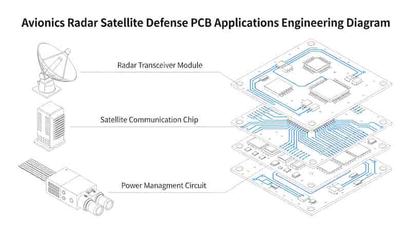
Best for: RF systems, 5G, aerospace, high‑speed data transmission.
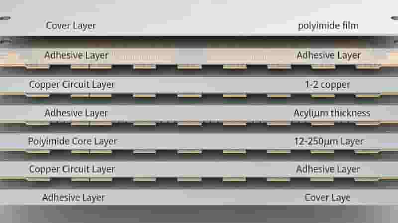
4. Polyimide PCB
Polyimide is the top flexible PCB material for dynamic, compact, and high‑temperature applications.
Advantages: Highly flexible, heat resistant up to 260°C, thin and lightweight.
Disadvantages: Higher cost than FR‑4.
Best for: Wearables, medical devices, aerospace, rigid‑flex circuits.
5. Ceramic PCB
Ceramic substrates provide extreme thermal conductivity and stability for harsh environments.
Advantages: Excellent heat dissipation, high voltage insulation, reliable in extreme conditions.
Disadvantages: High cost, brittle structure.
Best for: High‑power RF, aerospace, defense, medical imaging.
How to Choose the Right PCB Material
Select your PCB material based on these key factors:
- Application Type: High‑frequency → Rogers; High‑power → MCPCB/ceramic; Flexible → polyimide; General → FR‑4
- Thermal Needs: Heat‑heavy designs need MCPCB or ceramic
- Flexibility: Dynamic devices require polyimide
- Budget: FR‑4 is most economical; specialty materials cost more
- Manufacturing: We support all prototype PCB material types
PCB Material Comparison Table
| Material | Cost | Thermal Performance | Best For |
| FR‑4 | Low | Standard | General prototypes |
| Metal Core | Medium | Excellent | High power & LEDs |
| Rogers | High | Good | High frequency / RF |
| Polyimide | Medium‑High | Good | Flex & wearables |
| Ceramic | High | Superb | Extreme environments |
Conclusion
Choosing the right PCB material directly determines your prototype’s success. FR‑4 offers value for general use, metal core PCBs improve thermal management, Rogers supports high‑frequency performance, polyimide enables flexibility, and ceramic delivers reliability in harsh conditions.
We specialize in high‑quality PCB prototype manufacturing with all major materials, ensuring your design performs as intended.
Need a Professional PCB Prototype?
Tell us your PCB material and design requirements for a free, no‑obligation quote.
Request a Quote Now
PCB Terminology Glossary – Over 150 Essential PCB Terms for Engineers & Global Buyers
What Are Tented Vias? A Complete PCB Design Guide
PCB Manufacturing and Assembly for Aerospace and Defense: IPC Class 3, Mil-Spec & AS9100 Solutions
Types of Flexible Circuit Boards: The Ultimate Guide to Flex PCBs
How to Choose a Reliable PCB Manufacturer in Europe: Complete Guide for Industrial Buyers