FR-4 is the global industry-standard flame-retardant glass-reinforced epoxy laminate for rigid printed circuit boards. Defined by NEMA LI-1 and IPC-4101, it delivers balanced electrical insulation, mechanical strength, thermal stability, UL94 V-0 flame resistance, and cost efficiency for industrial, automotive, telecom, and consumer electronics.
What is FR-4 Material?
FR-4 (Flame Retardant Type 4) is a material grade defined by NEMA, not a specific product name. FR stands for flame retardant, meaning the resin self-extinguishes after combustion, complying with UL94 V-0.
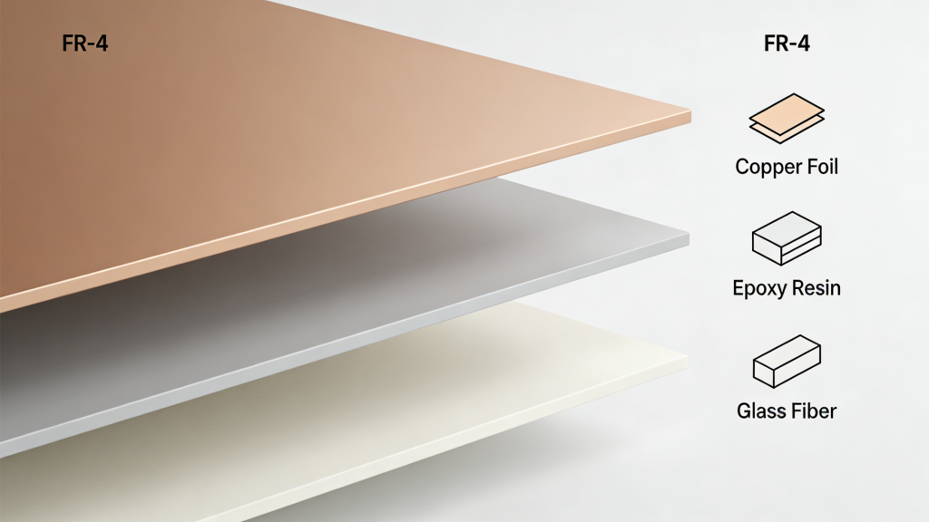
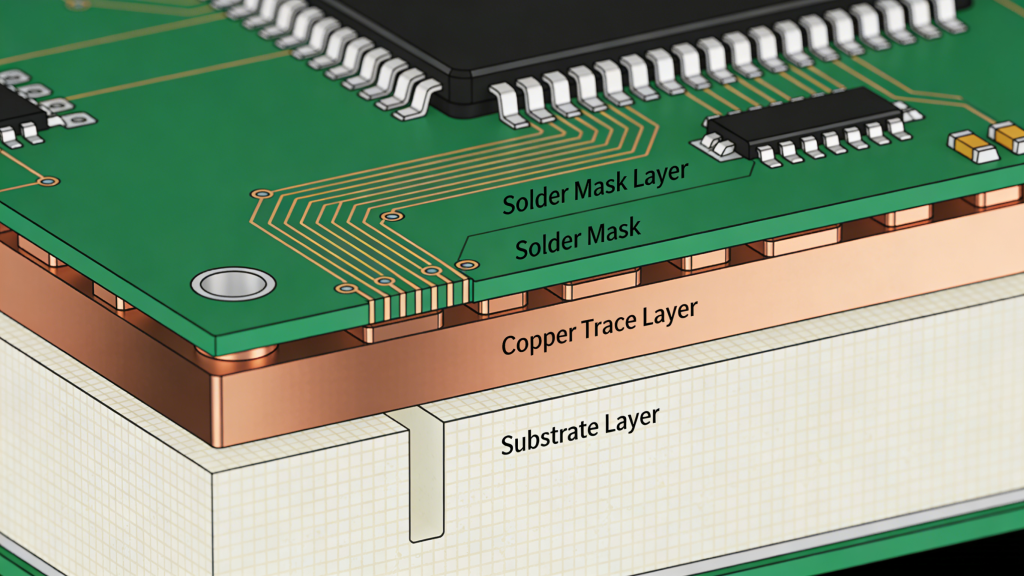
It is a composite made from electronic-grade glass fiber cloth reinforced with epoxy resin, bonded and hot-pressed with copper foil to form Copper Clad Laminate (CCL) — the core base material for rigid PCBs.
Composition & Structure of FR-4
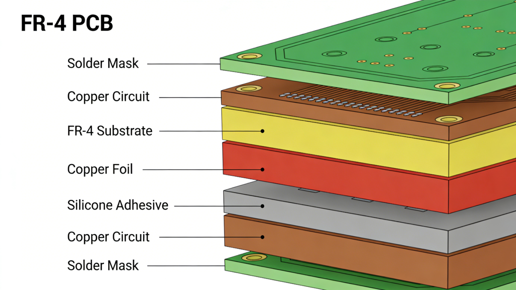
A standard FR-4 PCB laminate consists of:
- Glass fiber cloth (reinforcement layer)
- Epoxy resin (adhesive & flame-retardant matrix)
- Copper foil (conductive layer, 18–70 μm)
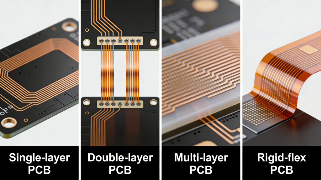
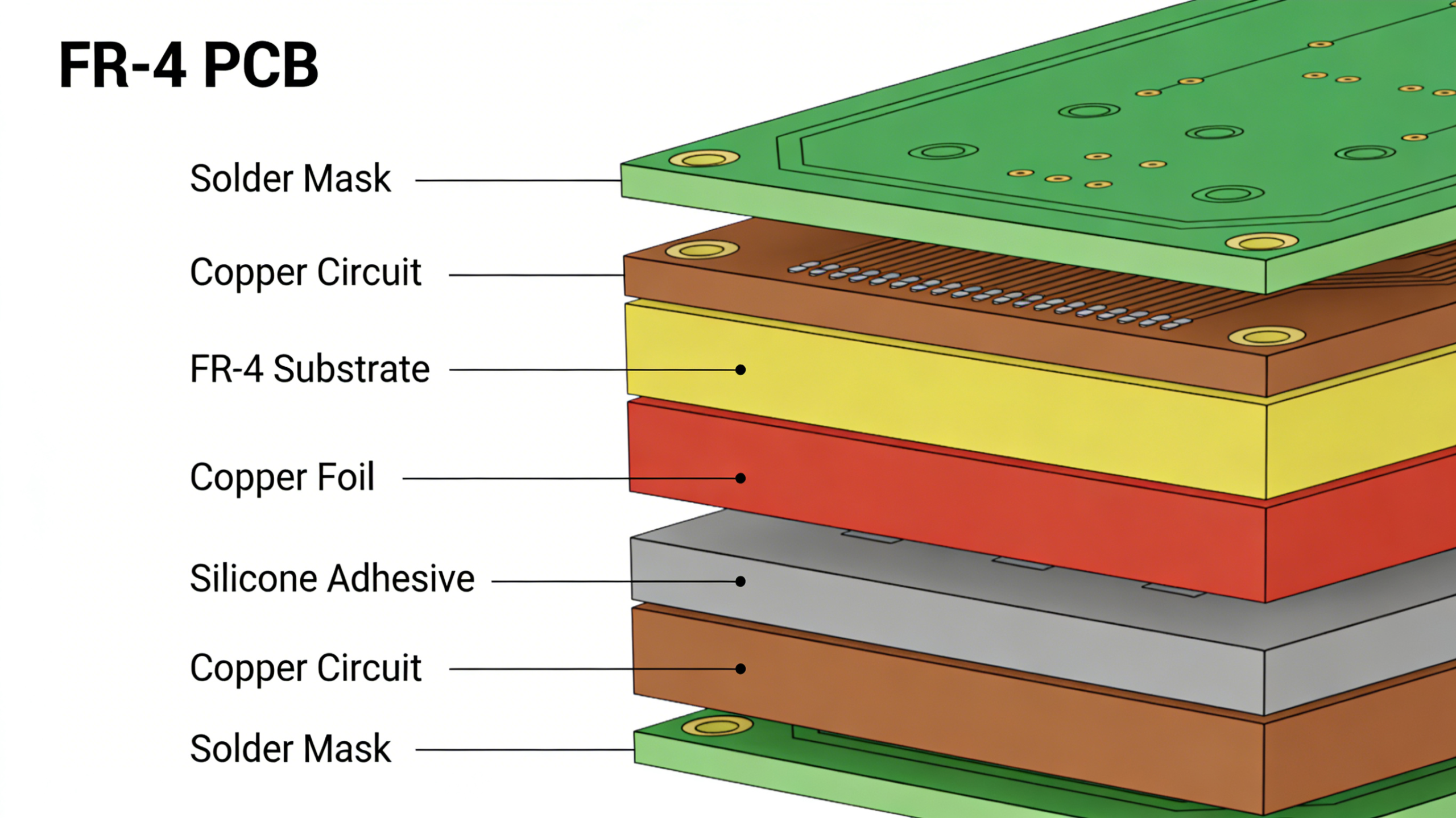
Multilayer printed circuit boards PCBs stack multiple FR-4 prepregs and cores with etched copper circuits, bonded under high temperature and pressure.
Key Performance Characteristics
FR-4 provides balanced electrical, mechanical, and thermal properties ideal for mass production:
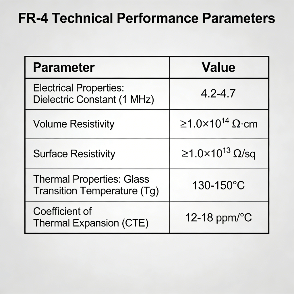
- Flammability: UL94 V-0 (self-extinguishing)
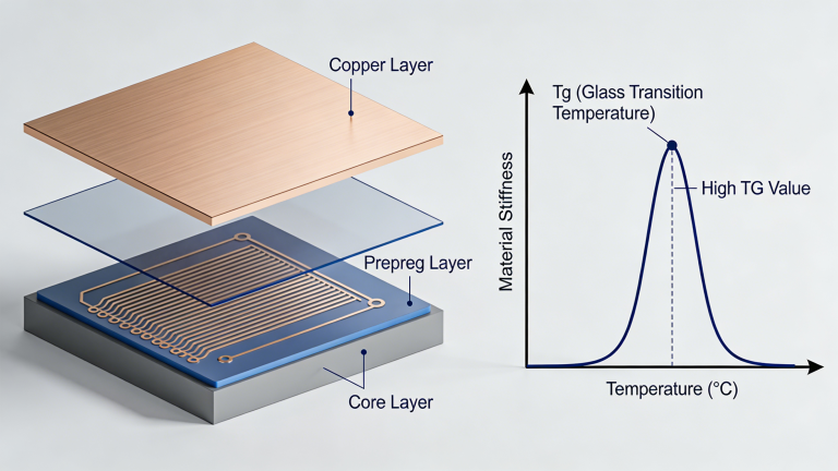
- Tg (glass transition): 130°C, 140°C, 150°C, 170°C, 180°C
- Dielectric constant (@1MHz): ~4.4
- Dissipation factor: ≤0.04
- Volume resistivity: ≥10⁸ Ω·cm
- Water absorption: ≤0.15%
- Tensile strength: ≥340 MPa
FR-4 Material Grades & Applications
FR-4 is classified by performance, Tg, and application:
- A1 Grade: High-end industrial, automotive, telecom
- A2 Grade: General industrial, advanced consumer electronics
- A3 / AB Grade: Home appliances, consumer electronics
- High Tg (>170°C): Automotive, power, high-reliability devices
- Halogen-free FR-4: RoHS, green electronics
Standard FR-4 Thickness & Copper Weight
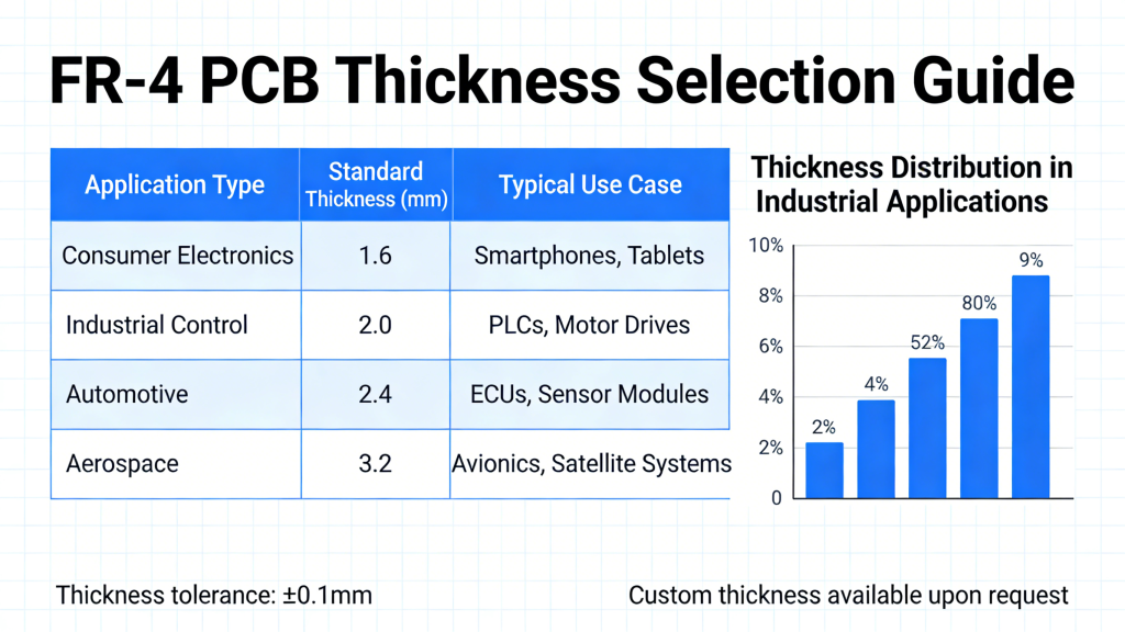
Common FR-4 thicknesses (mm): 0.3, 0.4, 0.5, 0.6, 0.8, 1.0, 1.2, 1.5, 1.6, 2.0
Standard copper weights: 0.5 oz, 1 oz, 2 oz
Thickness selection depends on space, weight, impedance matching, and component mounting.
FR-4 vs Other PCB Substrates
| Material | Flame Retardant | Tg Typical | Best For |
|---|---|---|---|
| FR-4 | UL94 V-0 | 130–180°C | Rigid PCBs, multilayer, industrial |
| CEM-3 | V-1 | 120°C | Single/double-sided PCB low-cost |
| FR-2 | V-1 | 105°C | Low-end consumer goods |
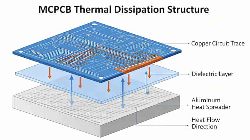
| Aluminum PCB | V-0 | — | High-power LED, thermal management |
How to Choose the Right FR-4 for Your Design
Select FR-4 based on:
- Operating temperature → choose Tg grade
- Signal speed → DK/DF requirements
- Reliability → military, automotive, commercial
- Cost → balance performance and budget
- Environmental → halogen-free if needed
For high-frequency or high-speed designs, consider high-speed low-loss FR-4 variants.
Conclusion
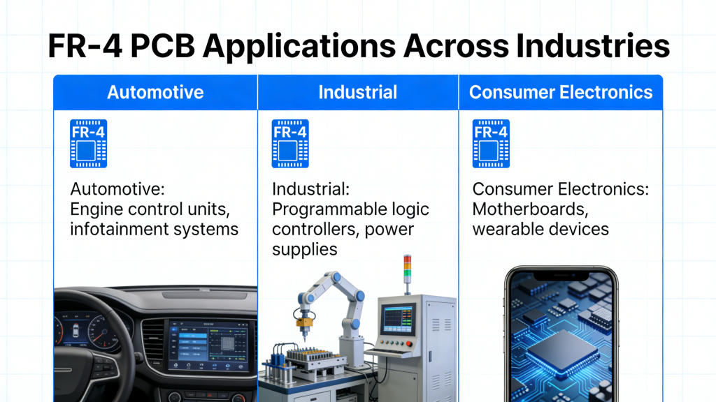
FR-4 remains the most versatile, cost-effective, and widely used substrate for rigid PCBs. Its balanced electrical, mechanical, and thermal properties make it ideal for nearly every electronics sector, from consumer devices to industrial and automotive systems.
Selecting the right FR-4 grade, Tg, thickness, and copper weight ensures your PCB meets performance, reliability, and cost targets.
Start Your FR-4 PCB Project Today
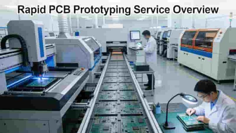
We provide professional FR-4 PCB fabrication, rapid prototyping, and full assembly with DFM analysis and 100% quality inspection.
Request a Quote
How to Choose the Best Metal Core PCB Manufacturer for Your Project
Prototype PCB Assembly Service – Fast, Reliable & Turnkey Solutions
Understanding Plated Half-Holes (Castellated Holes) in PCB Design
Flexible PCB Manufacturing and Assembly: The Complete 2025 Guide
PCB Solder Mask: The Complete Professional Guide to Solder Resist Technology