Summary: This professional PCB classification guide helps engineers and procurement teams understand PCB types by layers, materials, flexibility, and applications. It provides clear selection criteria to balance performance, cost, and reliability for global industrial projects.
Why Understanding PCB Classification Matters
Printed Circuit Boards (PCB) are the backbone of modern electronics, serving as the foundation for connecting and supporting components in devices ranging from smartphones to industrial machinery. Choosing the right PCB type is critical to achieving optimal performance, cost-efficiency, and design flexibility in your project.
PCB classification based on layer count, substrate material, and application scope guides engineers and designers in selecting the most suitable board for specific needs, whether it is a low-cost single-sided PCB for basic electronics or a complex multilayer PCB for advanced applications.
What is a PCB?
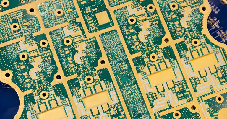
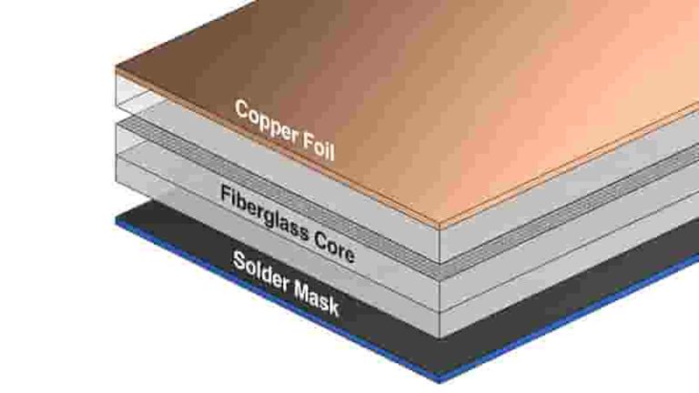
A Printed Circuit Board (PCB) is a fundamental component in modern electronics, acting as a platform to connect and support electronic components such as resistors, capacitors, and microchips. It consists of a non-conductive substrate, typically made of fiberglass or plastic, with conductive copper traces printed onto its surface to form electrical pathways.
These pathways enable signals and power to flow between components, ensuring devices like smartphones, computers, and medical equipment function reliably. PCB technology eliminates messy manual wiring and enables mass production of consistent electronic assemblies.
PCB Classification Overview
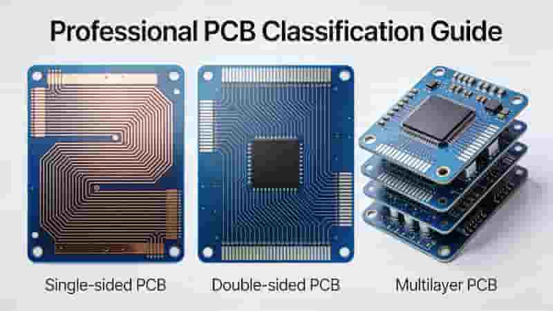
PCBs are classified based on three primary dimensions: layer count, substrate material, and application scope. These categories help engineers select the right PCB type to meet specific project requirements, such as circuit complexity, physical constraints, or environmental conditions.
- Layer Count: Defines circuit density and design complexity
- Substrate Material: Determines rigidity, flexibility, and heat resistance
- Application Scope: Matches signal frequency and environmental demands
Classification by Layer Count
PCB classification by layer count determines the board’s capacity to support varying levels of circuit complexity. Based on the number of conductive layers, PCBs are categorized into single-sided, double-sided, and multilayer types.
Single-sided PCB
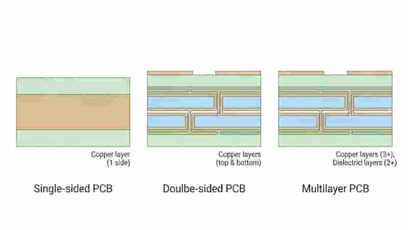
A single-sided PCB features conductive copper traces on one side of a non-conductive substrate. This design simplifies manufacturing and minimizes costs, making it ideal for basic electronics with straightforward circuit requirements.
Applications: Remote controls, simple calculators, basic home appliances
Double-sided PCB
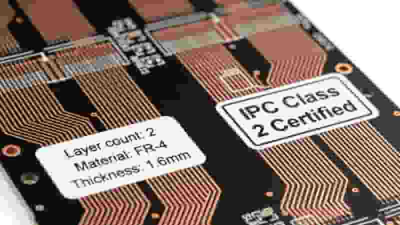
Double-sided PCBs have copper traces on both sides of the substrate, connected through vias. This configuration doubles the design space compared to single-sided boards, enabling more complex circuits while reducing electromagnetic interference.
Applications: Consumer electronics, automotive dashboards, power supplies
Multilayer PCB
Multilayer PCBs consist of three or more conductive layers, laminated together with insulating material. They support high-density circuits, making them essential for advanced electronics requiring compact designs and robust performance.
Applications: Smartphones, medical devices, aerospace systems
| PCB Type | Layers | Advantages | Applications | Cost |
|---|---|---|---|---|
| Single-sided | 1 | Low cost, simple manufacturing | Remote controls, basic appliances | Low |
| Double-sided | 2 | Moderate complexity, reduced EMI | Consumer electronics, automotive | Medium |
| Multilayer | 3+ | High density, compact design | Smartphones, medical devices | High |
Classification by Substrate Material
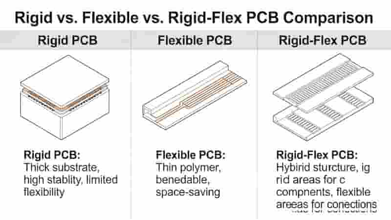
The substrate material of a PCB defines its mechanical properties, influencing its suitability for specific applications. PCBs are classified into rigid, flexible, and rigid-flex types based on their base materials.
Rigid PCB
Rigid PCBs use solid, non-bendable substrates like FR-4, CEM-1/3, or metal-based materials such as aluminum. These boards provide excellent mechanical strength and stability, ideal for fixed installations.
Flexible PCB (FPC)
Flexible PCBs are made from pliable materials like polyimide, allowing them to bend and conform to unique shapes. This enables compact and lightweight designs perfect for space-constrained devices.
Rigid-Flex PCB
Rigid-flex PCBs combine rigid and flexible substrates, integrating durability with adaptability. This hybrid design supports complex 3D configurations and reduces the need for connectors.
Classification by Application Scope
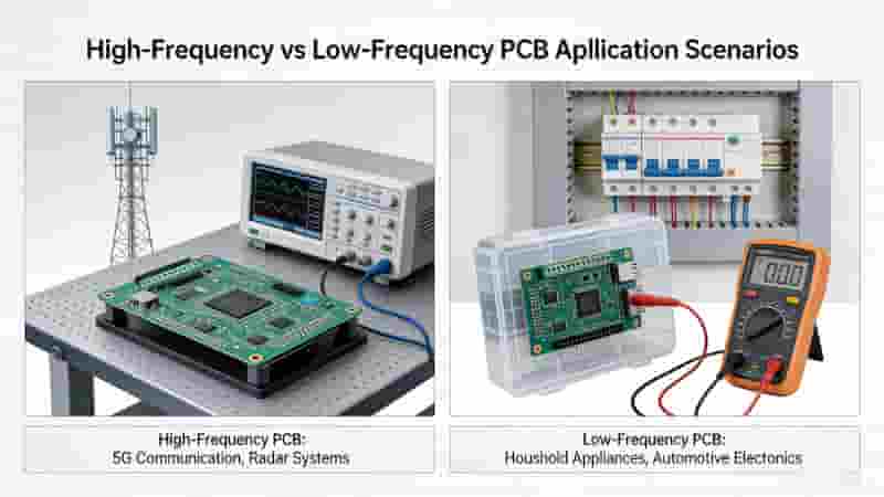
PCBs are also classified based on their application scope, particularly the frequency of signals they handle. This divides PCBs into high-frequency and low-frequency types.
High-frequency PCB
High-frequency PCBs operate above 1 GHz, using low-dielectric materials to minimize signal loss. Critical for 5G, radar, and satellite systems where signal integrity is paramount.
Low-frequency PCB
Low-frequency PCBs operate below 1 GHz, using standard materials like FR-4. Cost-effective for household appliances, basic consumer electronics, and industrial controls.
PCB Manufacturing Basics
The manufacturing process transforms raw materials into functional PCB boards. Key steps include circuit design, photolithography, etching, lamination (for multilayer), drilling, plating, solder mask, and surface finishing.
Each step is tailored to the PCB type, ensuring performance, reliability, and consistency for industrial and commercial applications.
How to Choose the Right PCB Type
Selecting the right PCB type balances performance, cost, and design requirements. Key factors include:
- Circuit Complexity: Simple → single-sided; Advanced → multilayer
- Space & Weight: Compact devices → flexible or rigid-flex PCB
- Environmental Conditions: High heat → metal core; High speed → high-frequency PCB
- Budget: Balance cost and performance for your project
Conclusion
Understanding PCB classification helps you select the ideal board type for your electronic projects. By categorizing PCBs based on layer count, substrate material, and application scope, you can optimize performance, cost, and reliability for applications from consumer electronics to aerospace.
We specialize in manufacturing a full range of high-quality PCB solutions tailored to global industrial buyers. Our capabilities include single-sided to 32-layer multilayer boards, rigid, flexible, rigid-flex, and high-frequency PCBs for demanding applications.
Need a Custom PCB Solution?
Request a free quote or contact our engineering team for professional PCB design, manufacturing, and assembly support.
Get Free Quote
How to Effectively Clean PCB Assembled Boards for Optimal Performance
Impedance Control PCB Fabrication Services
Ultimate Guide to PCB Materials, Dielectric Strength, and Testing in 2025
Why Choose Affordable PCB Prototyping?
PCB Vias: Complete Guide to Types, Design, Reliability & Applications