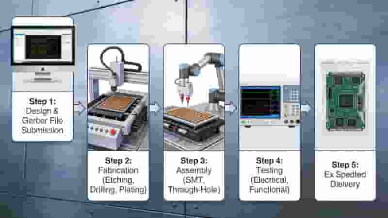
Gerber files are the universal manufacturing standard for PCB prototyping, defining copper traces, solder mask, silkscreen, drill data, and board geometry to ensure accurate, fast, and reliable fabrication.
What Are Gerber Files for PCB Prototyping?
Gerber files (RS‑274X standard) are vector‑based fabrication files that translate your CAD design into machine‑readable instructions for PCB prototyping. They carry complete layer data, aperture definitions, and coordinates without needing external D‑code files.
Using validated Gerber data eliminates reworks, shortens lead times, and ensures your prototype matches design intent precisely.
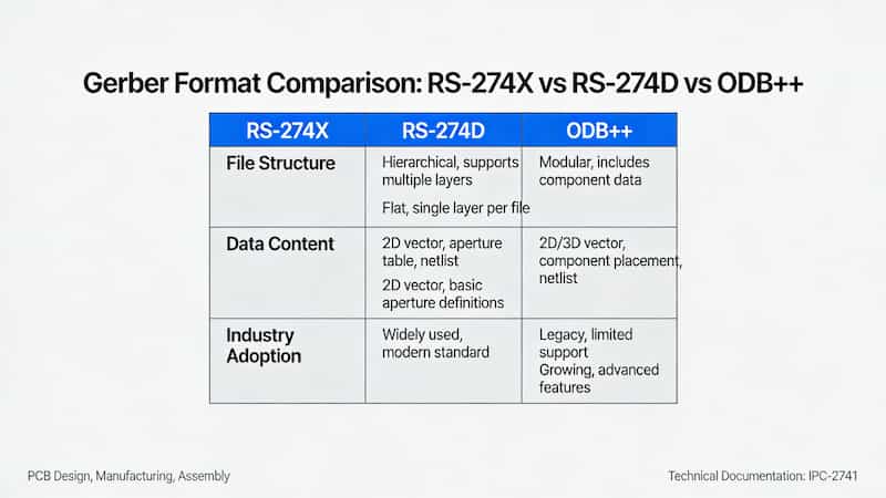
Gerber Formats & Compatibility for PCB Prototyping
Selecting the right format ensures smooth production and avoids delays in PCB prototyping.
| Format | Features | Best For | Compatibility |
|---|---|---|---|
| RS‑274X (Extended) | Embedded apertures, net support, regions | Most PCB prototypes | Universal |
| RS‑274D | Basic vectors, requires D‑codes | Legacy designs only | Limited |
| ODB++ / IPC‑2581 | Full design intent, stackup, BOM | High‑density HDI boards | Advanced fabs |
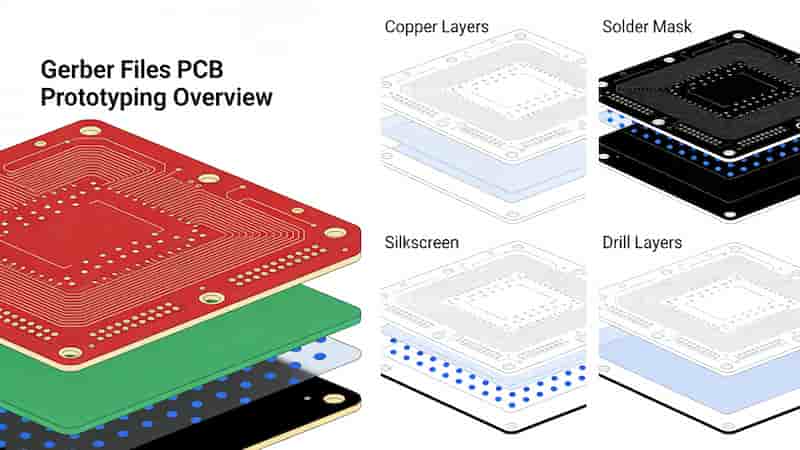
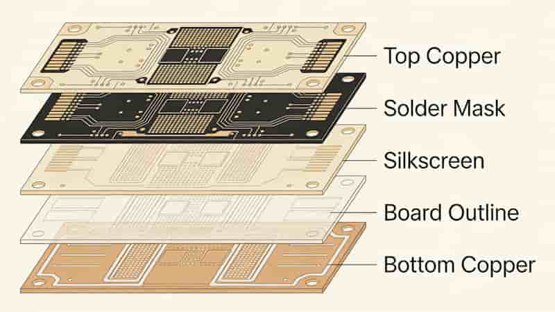
Essential Layers for Gerber Files in PCB Prototyping
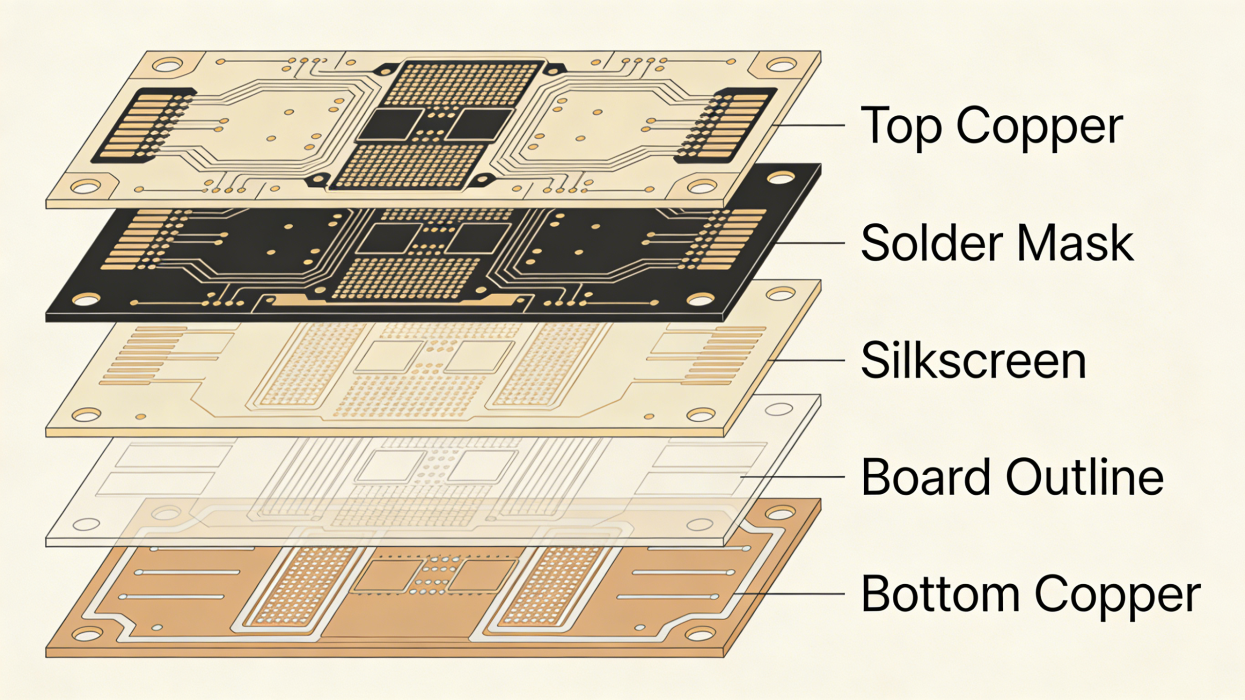
A complete Gerber package includes these critical layers for reliable PCB prototyping:
- Top & Bottom Copper (GTL, GBL)
- Top & Bottom Solder Mask (GTS, GBS)
- Top & Bottom Silkscreen (GTO, GBO)
- Top & Bottom Paste Mask (GTP, GBP)
- Board Outline / Edge Cuts (GKO)
- Excellon Drill File (DRL)
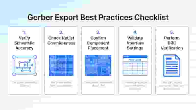
Gerber Export Best Practices for PCB Prototyping
Follow these rules to create production‑ready Gerber files for PCB prototyping:
1. Use RS‑274X with embedded apertures; avoid RS‑274D.
2. Keep consistent units (inch or mm) and precision (3:5 or 3:6) across all files.
3. Include all functional layers and omit unused internal layers.
4. Verify polarity for solder mask: openings align with pads.
5. Use a free Gerber viewer to check overlaps, registration, and clearances before ordering.
Common Gerber Mistakes That Delay PCB Prototyping
Avoid these errors to speed up PCB prototyping and reduce costs:
• Missing layers or incomplete drill files
• Inverted solder mask polarity causing open pads
• Unit mismatches between Gerber and NC drill
• Outdated RS‑274D without aperture lists
• Unchecked files leading to misalignment or re‑spins
Summary
Validated Gerber files are foundational for successful PCB prototyping. Using RS‑274X, including all required layers, verifying data, and standardizing export settings drastically reduce errors, lead times, and costs.
We support all standard Gerber workflows and provide fast, reliable PCB prototyping for global engineers and buyers.
Need Reliable PCB Prototyping?
Upload your Gerber files for a free, instant quote. We deliver high‑quality prototypes with fast lead times and full technical support.
Request a Quote
Metal Core PCB (MCPCB) Manufacturing Service in China
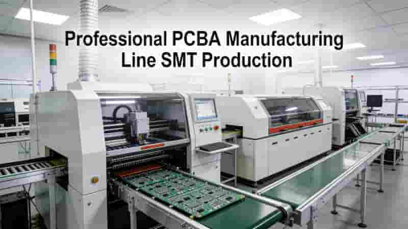
Printed Circuit Board Assembly Services | Full Turnkey PCBA Solutions

What Is the Tg Value of PCB Substrate? A Complete Guide for 2025 Designs
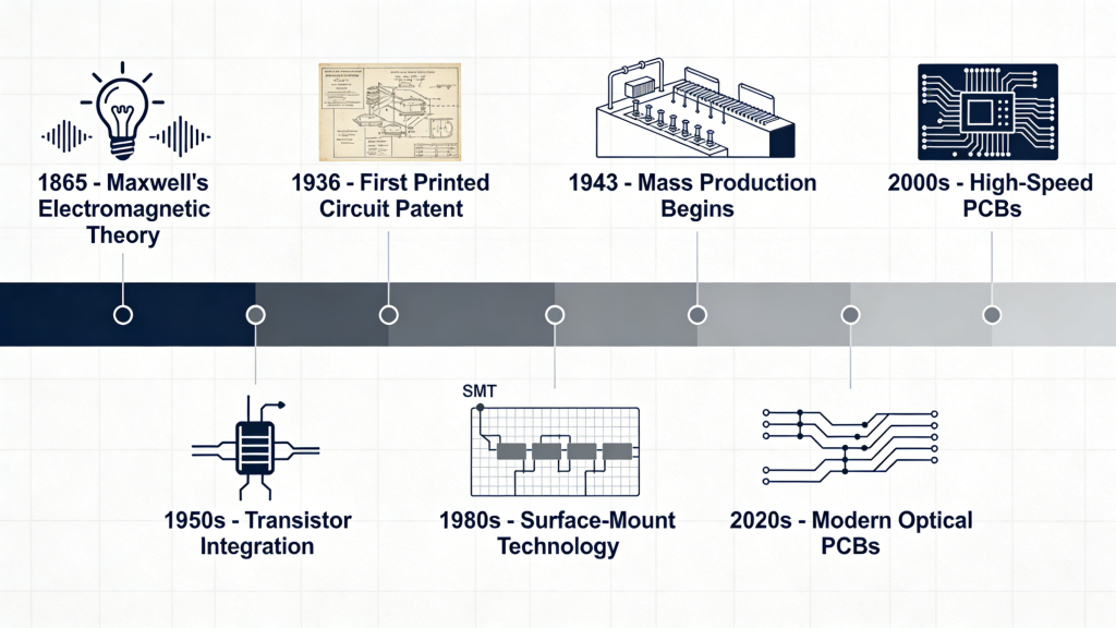
The Historical Timeline and Future Outlook of Printed Circuit Boards
UK PCB Prototype Manufacturing: Fast Turnaround, Cost-Effective & IPC-Certified Quality