|

PCB Prototype Manufacturing: The Complete 2025 Technical Guide for Engineers & Buyers 

PCB Prototype Quality Testing - AOI Electrical Impedance Verification

PCB prototype manufacturing is the critical first step in electronic product development. This professional guide covers full processes, materials, DFM, testing, standards, and selection tips to help you build reliable, production-ready prototypes efficiently.

Introduction to PCB Prototypes

PCB prototype manufacturing validates design functionality, optimizes performance, and reduces risks before mass production. For engineers and procurement teams, high-quality prototypes ensure products meet performance, reliability, and cost targets.

What Is a PCB Prototype?

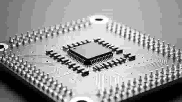
A PCB prototype is a preliminary circuit board used to test design feasibility, electrical performance, and mechanical fit. It helps detect flaws early, cutting development time and lowering overall costs.

PCBs use etched copper on insulating substrates to connect components. Prototypes replicate final production behavior to validate real‑world performance.

PCB Prototype Board Overview - Single Double Multi-layer PCB Design

Types of PCB Prototypes

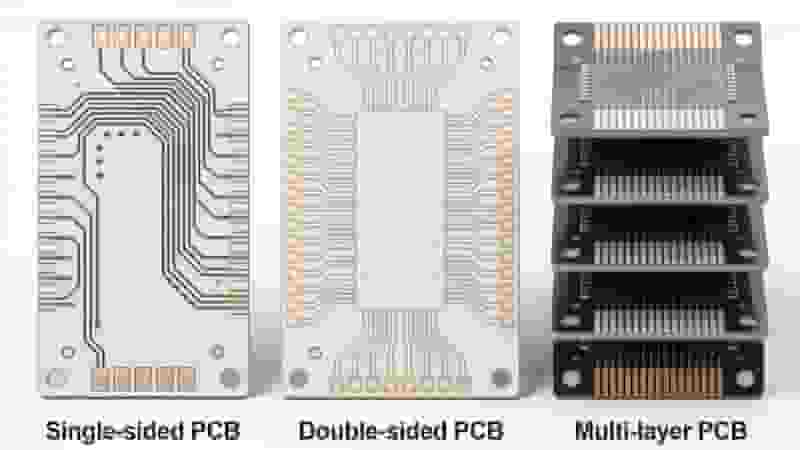
Single‑sided PCB Prototypes – Components and traces on one side; ideal for simple circuits.

Double‑sided PCB Prototypes – Traces on both sides connected by vias; balanced density and cost.

Multi‑layer PCB Prototypes – Stacked inner layers for high‑density electronics; used in industrial and smart devices.

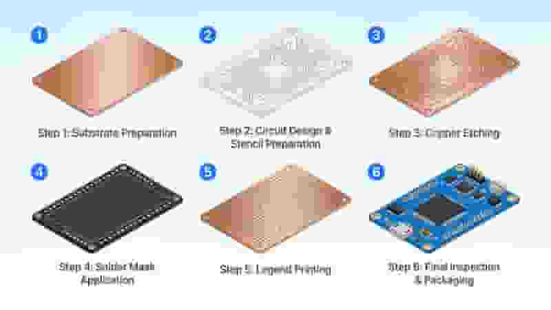
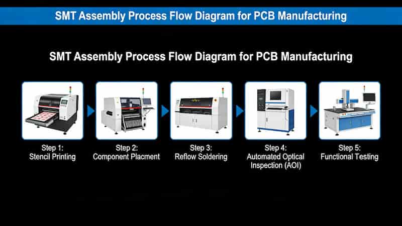
Full PCB Prototype Manufacturing Process

1. Design & File Preparation: CAD layout, Gerber files, DFM check.

2. Printing & Photomask: Transfer design to the substrate.

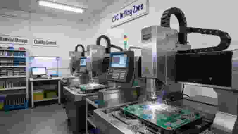
3. Drilling: Precision holes for vias and components.

4. Plating: Copper deposition for conductive paths.

5. Etching: Remove excess copper to form circuits.

6. Solder Mask & Silkscreen: Protection and labeling.

7. Surface Finish: HASL, ENIG, OSP, etc.

8. Electrical Testing & Assembly: Functional verification.

PCB Prototype Manufacturing Process Flow Chart - Full Production Steps

Materials & Specifications

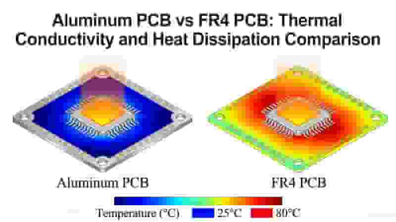
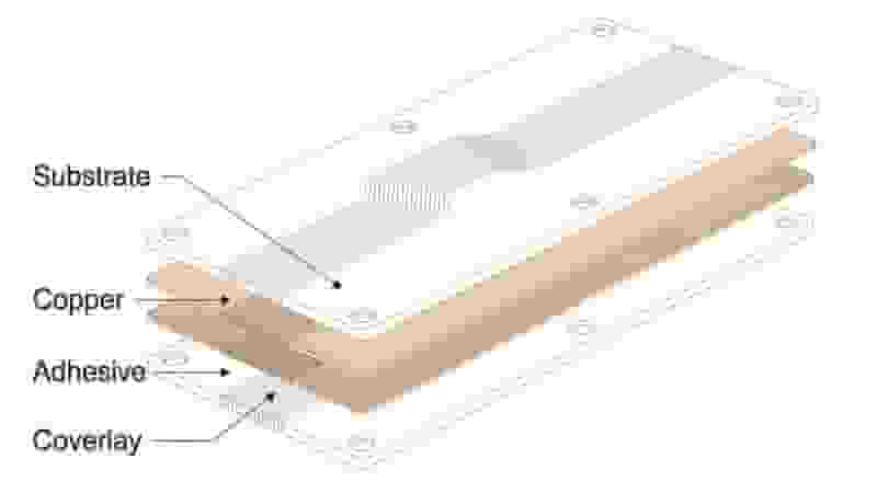
Common substrates: FR‑4, High‑Tg FR‑4, Aluminum, Rogers, Flexible PI.

Copper thickness: 1/3oz to 2oz.

Trace width / spacing: Down to 3mil / 3mil for high‑density designs.

DFM Guidelines for PCB Prototypes

Optimize tolerances for PCB prototype manufacturing stability.

Standardize via size and annular rings.

Avoid overly complex structures that raise cost and lead time.

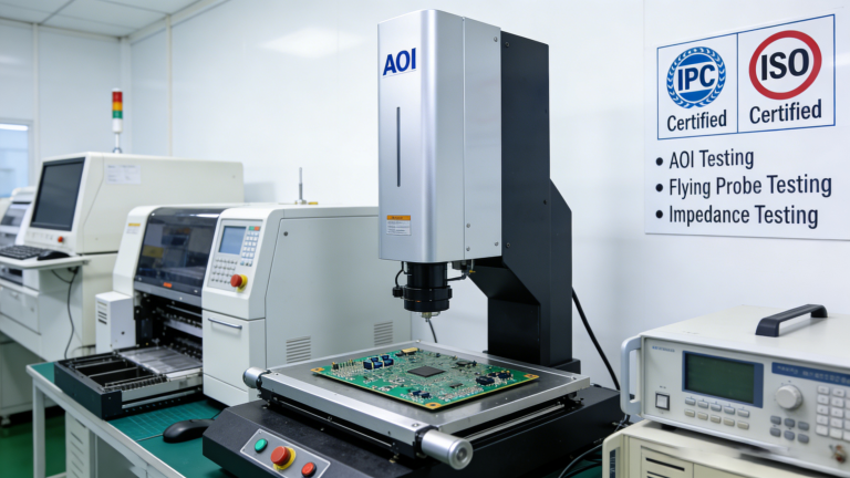
Testing & Quality Control

AOI – Automated Optical Inspection

Electrical continuity & isolation test

Impedance test (for high‑frequency boards)

Thermal & reliability validation

PCB Prototype Quality Testing - AOI Electrical Impedance Verification

How to Choose a PCB Prototype Manufacturer

• Technical capability for PCB prototype manufacturing

• Quality system & certification

• Quick turnaround (24hr–5days)

• Competitive pricing

• Responsive engineering support

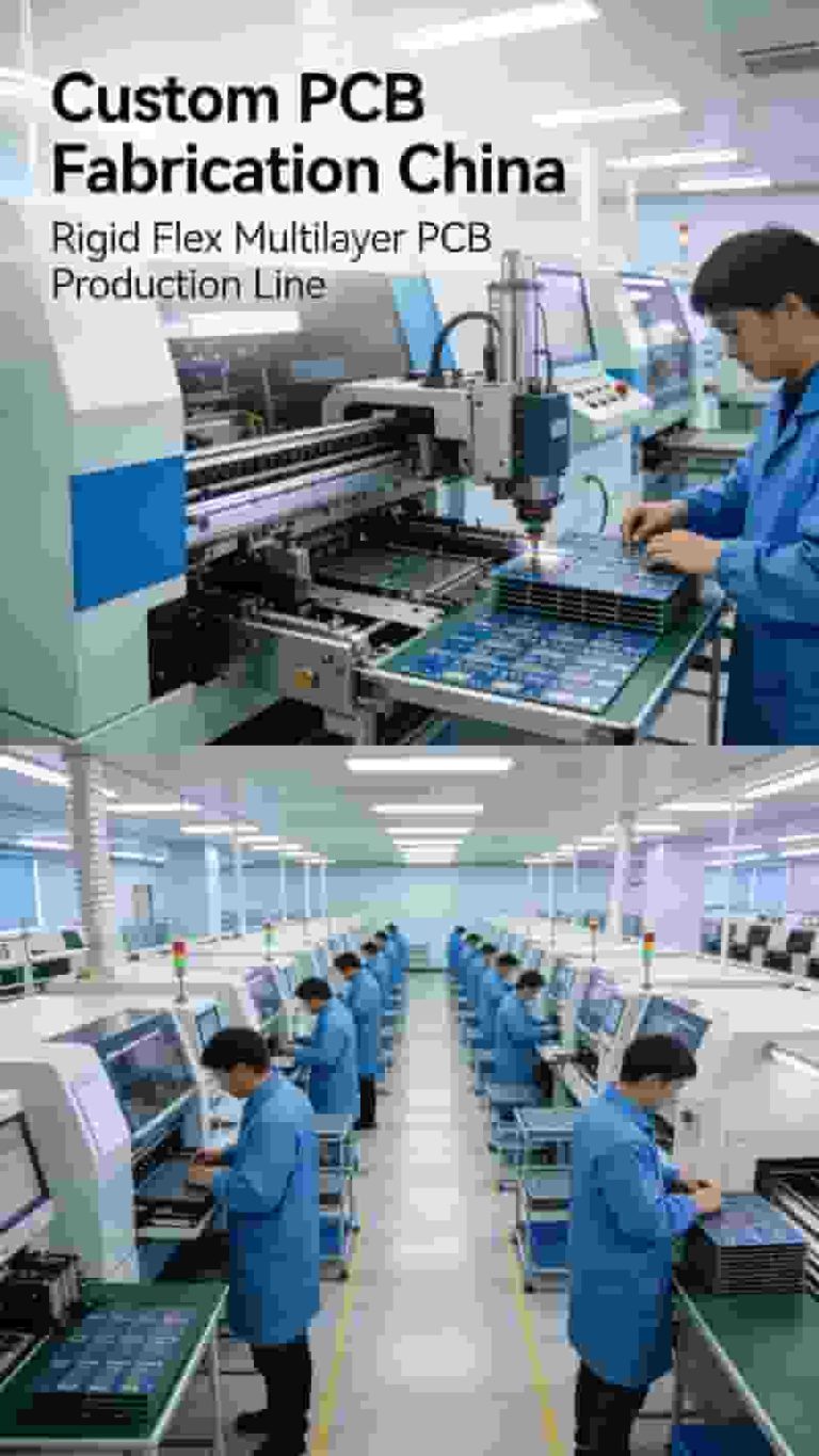
Our PCB Prototype Manufacturing Services

We provide full‑service PCB prototype manufacturing for global industrial buyers and engineers.

Supported types: Single‑sided, double‑sided, multilayer up to 20 layers

Surface finishes: HASL, ENIG, OSP, Immersion Silver, Gold Finger

Solder mask colors: Green, black, red, white, blue, yellow

Turnaround: Quick‑turn options as fast as 24 hours

Assembly: SMT & through‑hole prototype assembly available

PCB Prototype Surface Finish Options - HASL ENIG OSP Gold Finger

Summary

PCB prototype manufacturing is foundational to successful electronic development. Working with an experienced partner ensures reliable, on‑time, cost‑effective prototypes that accelerate your product launch.

Get Your PCB Prototype Quote Today

Send us your Gerber files and requirements for a free, fast quotation on PCB prototype manufacturing. We support quick‑turn, high‑quality, and fully customized solutions for global buyers.

Inquire Now | Custom PCB Prototype

Flexible PCB basic structure layers: substrate, copper, adhesive, coverlay

Complete Introduction to Flexible Circuit Board Materials

Posted on
0 Comments
Flexible circuit board materials directly define flexibility, thermal stability, electrical performance, and reliability of FPCs. This professional guide covers substrates, conductors, adhesives, protective layers, stiffeners, and selection standards for global industrial buyers, engineers, and procurement teams. What Are Flexible Circuit Boards A flexible circuit board (FPC) is a lightweight, bendable circuit built on flexible insulating…
SMT assembly process flow for PCB manufacturing

SMT vs SMD: What’s the Difference in PCB Assembly?

Posted on
0 Comments
SMT (Surface Mount Technology) and SMD (Surface Mount Device) are core concepts in PCB assembly. SMT is the automated assembly process for mounting components onto PCBs, while SMD refers to the miniaturized components used in this process. This guide clarifies their definitions, differences, workflow, and applications for global engineers and buyers. Introduction In the fast-evolving…
FR-4 PCB laminate structure cross section

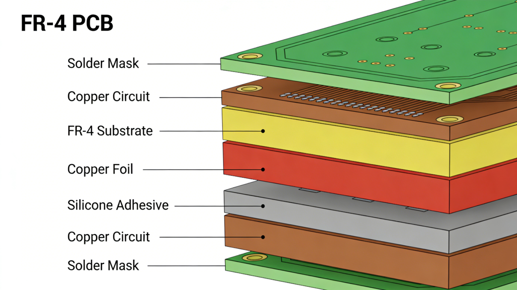
What is FR-4 Material in PCB Fabrication? Complete Engineering Guide

Posted on
0 Comments
FR-4 is the global industry-standard flame-retardant glass-reinforced epoxy laminate for rigid printed circuit boards. Defined by NEMA LI-1 and IPC-4101, it delivers balanced electrical insulation, mechanical strength, thermal stability, UL94 V-0 flame resistance, and cost efficiency for industrial, automotive, telecom, and consumer electronics. What is FR-4 Material? FR-4 (Flame Retardant Type 4) is a material…
Impedance Control PCB Manufacturing and TDR Testing Process

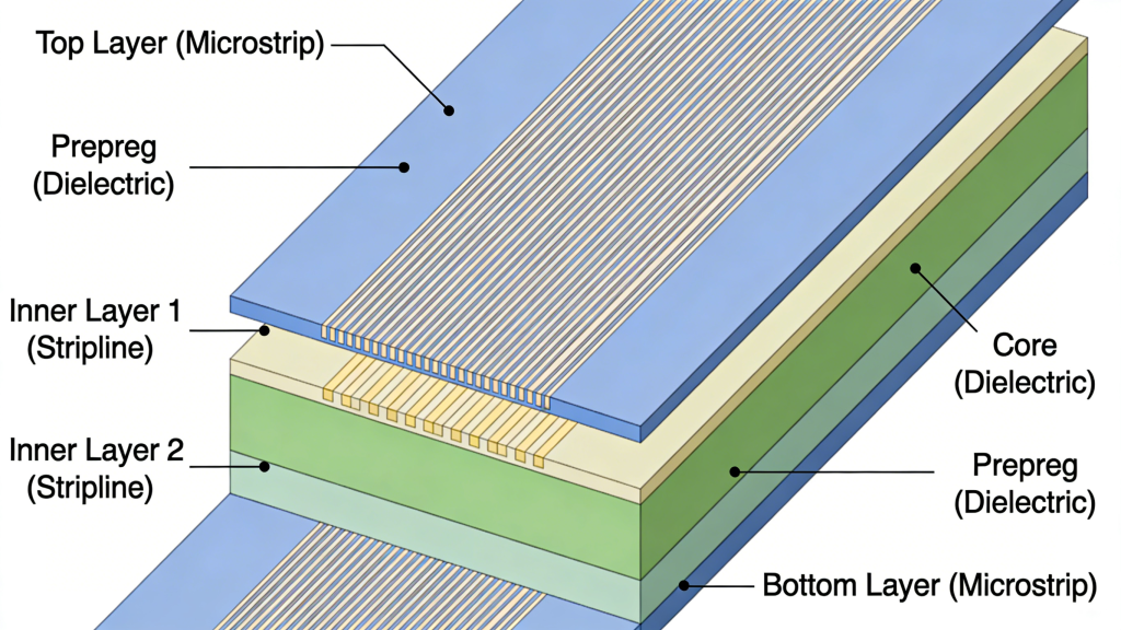
Impedance Control PCB Fabrication Services

Posted on
0 Comments
Advanced controlled impedance PCB manufacturing for high-speed, RF and telecom designs, delivering precise 50 Ω / 90-100 Ω impedance, tight tolerances and fast global turnaround. Tight-tolerance controlled impedance: 50 Ω single-ended and 90/100 Ω differential traces engineered for consistent signal integrity. Multilayer stackups with FR-4 and high-frequency materials (Rogers, hybrid) for complex high-speed designs. Full…
4 Types of PCB Open Circuit Diagram Repeated Gap Vacuum Scratched

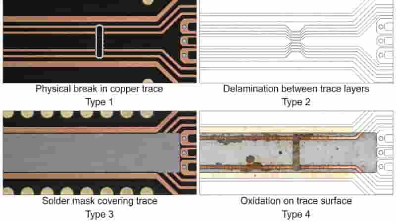
PCB Open Circuit: Causes, Types, Diagnosis & Proven Solutions

Posted on
0 Comments
PCB open circuit is one of the most frequent defects in PCB manufacturing, causing production downtime, rework, delivery delays, and quality complaints. This professional guide explains definitions, types, root causes, inspection methods, prevention, and reliable fixes for global electronics buyers and engineers. What Is a PCB Open Circuit? A PCB open circuit is an interruption…
Aluminum PCB and FR4 PCB thermal conductivity and heat dissipation effect comparison

Aluminum PCB vs FR4 PCB: Full Technical Comparison for Industrial & High-Power Applications

Posted on
0 Comments
Aluminum PCBs and FR4 PCBs are the most widely used substrate materials in modern electronics. This professional guide compares their thermal performance, mechanical strength, electrical properties, cost, and ideal applications to help engineers and purchasers select the optimal PCB solution for their projects. Material & Layer Structure FR4 PCBs are made of glass fiber reinforced…

Frequently Asked Questions

A: Single‑sided boards suit simple circuits. Multilayer boards support high‑density, high‑speed designs common in industrial electronics.

A: Standard 3–5 days; quick‑turn 24–48 hours for qualified designs.

A: Yes, we support custom materials, stackups, finishes, and assembly per your specifications.

Similar Posts