Aluminum PCBs and FR4 PCBs are the most widely used substrate materials in modern electronics. This professional guide compares their thermal performance, mechanical strength, electrical properties, cost, and ideal applications to help engineers and purchasers select the optimal PCB solution for their projects.
Material & Layer Structure
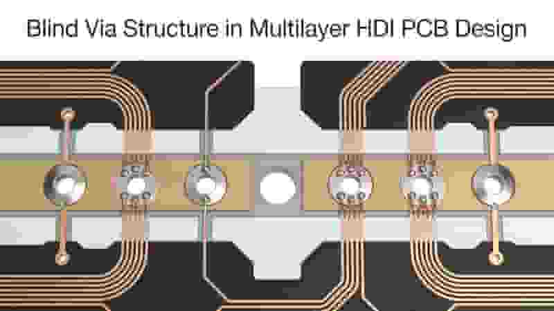
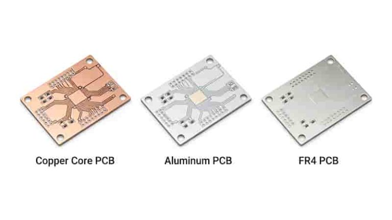
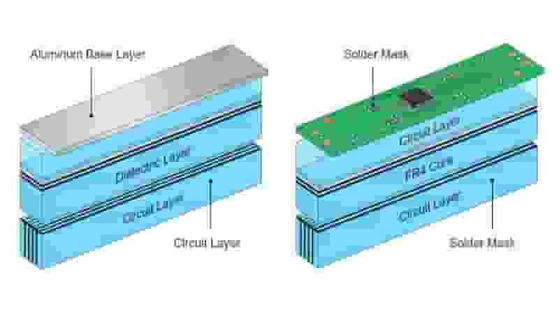
FR4 PCBs are made of glass fiber reinforced epoxy laminate, featuring flame retardant properties (UL94V-0). They support single-layer, double-layer, and multilayer designs up to 30 layers, offering high design flexibility for standard electronic products.
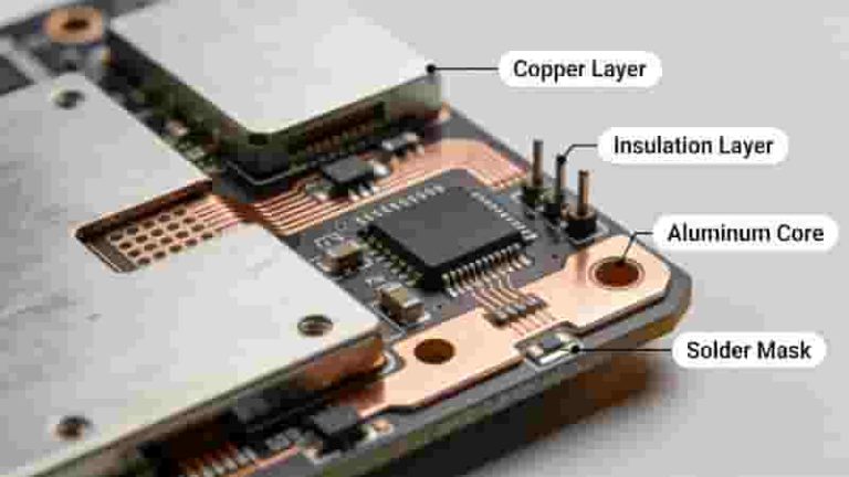
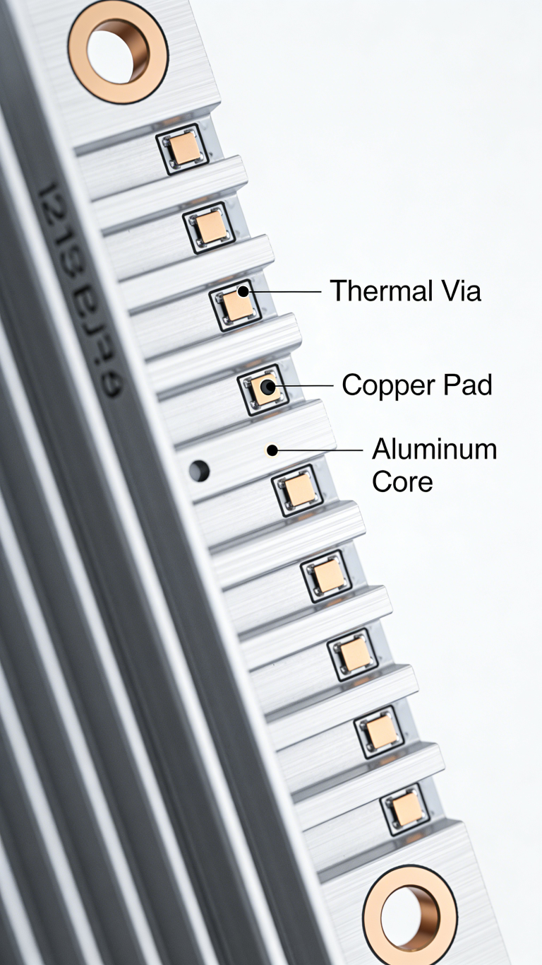
Aluminum PCBs (Metal Core PCB) adopt a three-layer structure: copper circuit layer, thermal conductive dielectric layer, and aluminum base layer. This unique structure provides excellent heat dissipation, making it the first choice for high-power and high-heat electronic equipment.
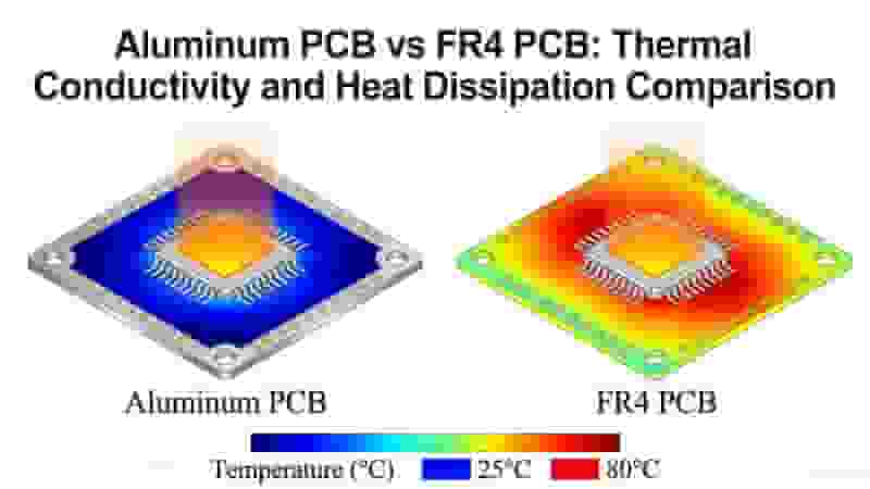
Thermal Performance Comparison
Thermal conductivity is the core difference between aluminum PCBs and FR4 PCBs. The thermal conductivity of aluminum substrate is about 600 times that of FR4, which can quickly export heat and avoid component overheating failure.
FR4 PCB thermal conductivity: 0.3 W/m·K, poor heat dissipation, not suitable for high-power applications.
Aluminum PCB thermal conductivity: 1.0-2.0 W/m·K (conventional type), high-power type up to 5.0-10 W/m·K, meeting the needs of high heat flux scenarios.
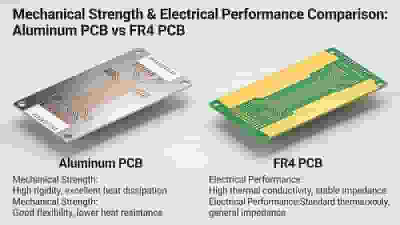
Mechanical & Electrical Properties
Aluminum PCBs have higher mechanical strength and rigidity, can resist vibration and impact, and are suitable for automotive and industrial control environments. The CTE is close to copper, reducing thermal stress damage.
FR4 PCBs have excellent dielectric properties, low loss factor, stable high-frequency performance, and are suitable for RF communication and high-speed signal transmission products.
FR4 CTE: 12-24 ppm/C; Aluminum PCB CTE: about 24 ppm/C, closer to copper’s 17 ppm/C.
Aluminum PCB vs FR4 PCB Full Comparison Table
| Parameter | Aluminum PCB | FR4 PCB |
|---|---|---|
| Thermal Conductivity | 1.0-10 W/m·K | 0.3 W/m·K |
| CTE (ppm/C) | ~24 (close to copper) | 12-24 |
| Max Operating Temp | -55C to 200C | -40C to 130C |
| Layer Structure | 3-layer fixed | Single to 30+ layers |
| Cost | Higher | Lower |
Pros & Cons of Aluminum PCB and FR4 PCB
Advantages of Aluminum PCBs
- Excellent thermal conductivity and heat dissipation
- High mechanical strength and rigidity
- Low thermal stress, long service life
- Wide operating temperature range
Disadvantages of Aluminum PCBs
- Higher manufacturing cost
- Limited layer and thickness options
- Special design rules required
Advantages of FR4 PCBs
- Low cost and high cost-performance ratio
- High design flexibility, multilayer support
- Excellent high-frequency electrical performance
- Mature manufacturing process
Disadvantages of FR4 PCBs
- Poor heat dissipation capacity
- CTE does not match copper well
- Limited high-temperature resistance
Ideal Application Scenarios
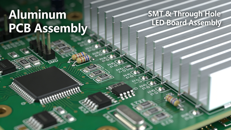
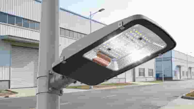
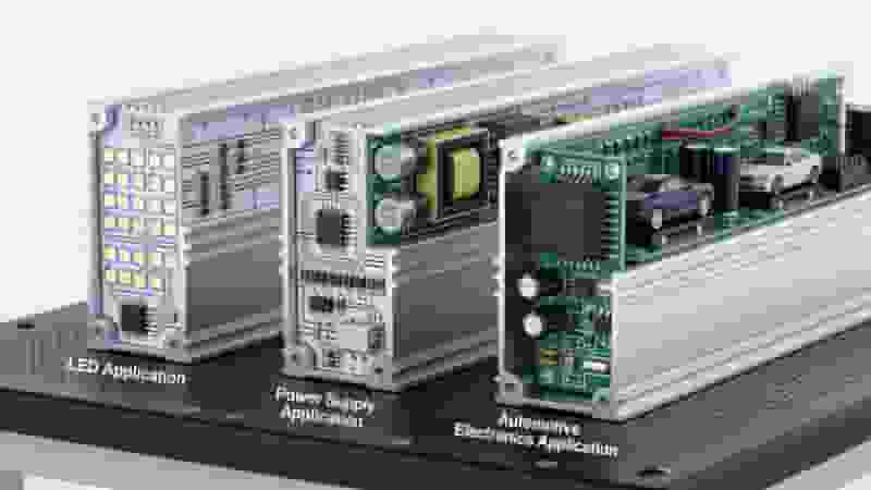
Aluminum PCBs are suitable for high-power, high-heat, and high-reliability scenarios:
- High-power LED lighting systems
- Switching power supplies, inverters, converters
- Automotive electronics, aerospace equipment
- Industrial control, motor drives
- 5G communication base stations, high-power microwave equipment
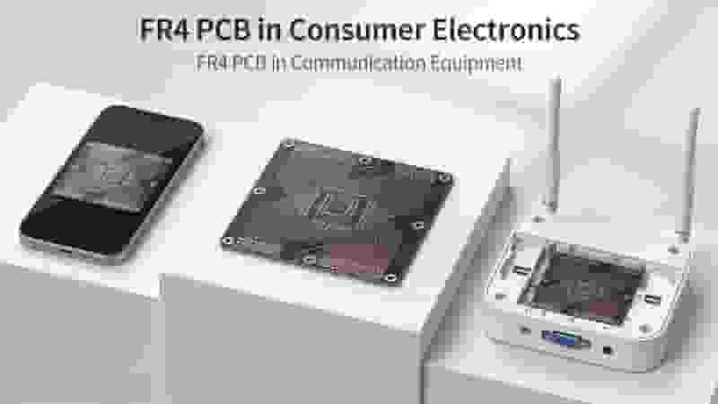
FR4 PCBs are suitable for cost-sensitive, high-frequency, and standard electronic products:
- Consumer electronics: mobile phones, laptops, home appliances
- High-speed computing, motherboard, graphics card
- IoT sensors, wearable devices
- RF wireless communication, WiFi/Bluetooth modules
- Low-to-medium power industrial control products
PCB Material Selection Guide
Choose Aluminum PCBs if your project meets these conditions:
- Operating temperature exceeds 125C
- High power density, large heat generation
- Harsh environment with vibration and impact
- Require long-term reliability and stability
Choose FR4 PCBs if your project meets these conditions:
- Low-to-medium power, low heat generation
- Require multilayer and high-density design
- High-frequency signal transmission needs
- Strict cost control, mass production
Conclusion
Aluminum PCBs and FR4 PCBs each have unique advantages and application fields. Aluminum PCBs dominate high-power and high-heat scenarios with excellent thermal performance, while FR4 PCBs maintain the mainstream position of general electronics with cost-effectiveness and design flexibility.
Selecting the right PCB material can significantly improve product performance, reliability, and cost control. We provide professional PCB design, manufacturing, and assembly services to support customized solutions of aluminum substrates and FR4 materials to meet your global export needs.
Get Custom PCB Solution & Free Quote
Contact us for Aluminum PCB and FR4 PCB manufacturing, customized design, and competitive export pricing.
Inquiry Now
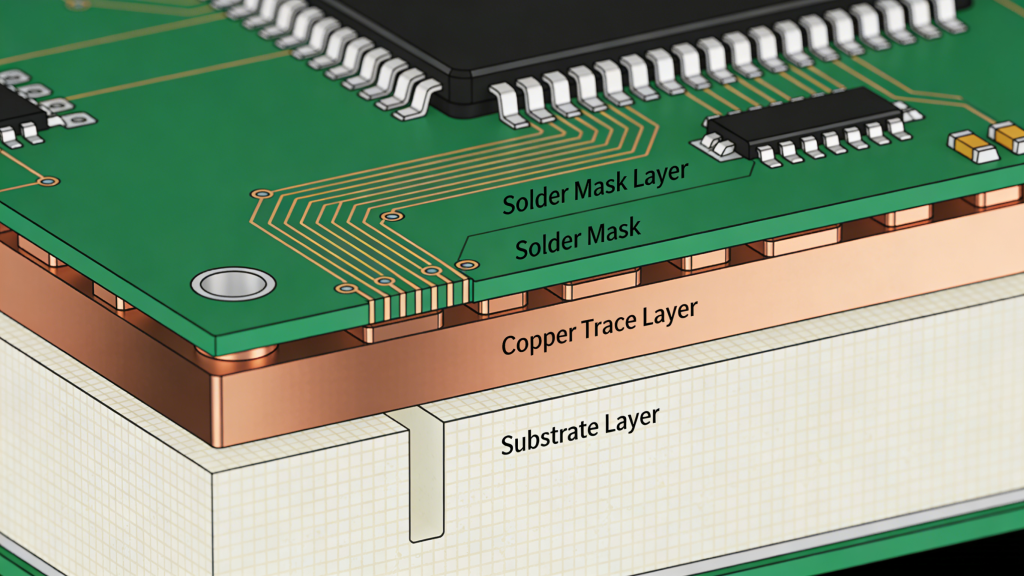
PCB Solder Mask: The Complete Professional Guide to Solder Resist Technology
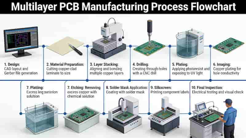
Multilayer PCB Prototyping & Manufacturing Services | Fast & Reliable
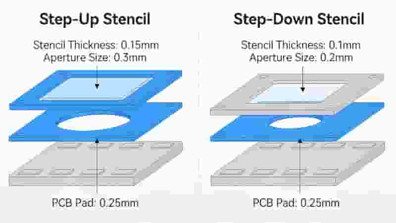
Step Stencil Manufacturing | Precision Multi-Level SMT Stencils
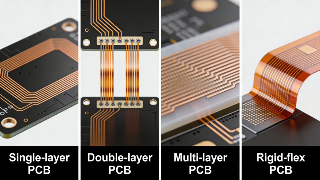
Transform Ideas into Reality with High-Quality Flex PCB Prototyping
Flying Probe Testing for PCB: The Complete Professional Guide