This professional guide details the full PCB fabrication process with engineering-grade steps, quality controls, and technical specifications for industrial buyers, engineers, and global procurement teams. Learn how reliable PCB manufacturing ensures consistency, performance, and compliance for export projects.
Pre-Production Engineering & DFM Review
Every professional PCB fabrication process starts with engineering validation. We perform full DFM/DFT checks, CAM file optimization, and layer alignment verification to eliminate production risks before manufacturing begins.
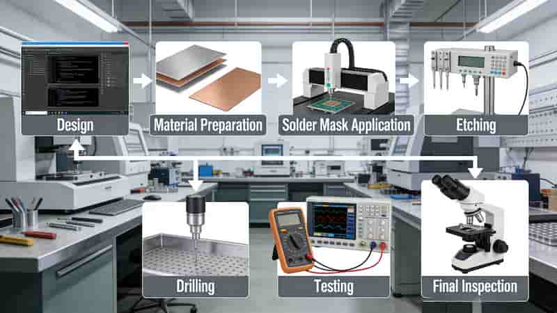
Key checks include Gerber/ODB++ validation, drill map consistency, impedance control planning, and material traceability. This step reduces rework and ensures your boards match IPC‑A‑600 and IPC‑6012 standards.
Inner Layer Imaging & Chemical Etching
Inner layers form the core circuitry of multilayer PCB manufacturing. Cleaned copper-clad laminates receive photoresist coating, UV exposure via LDI, and development to define trace patterns.
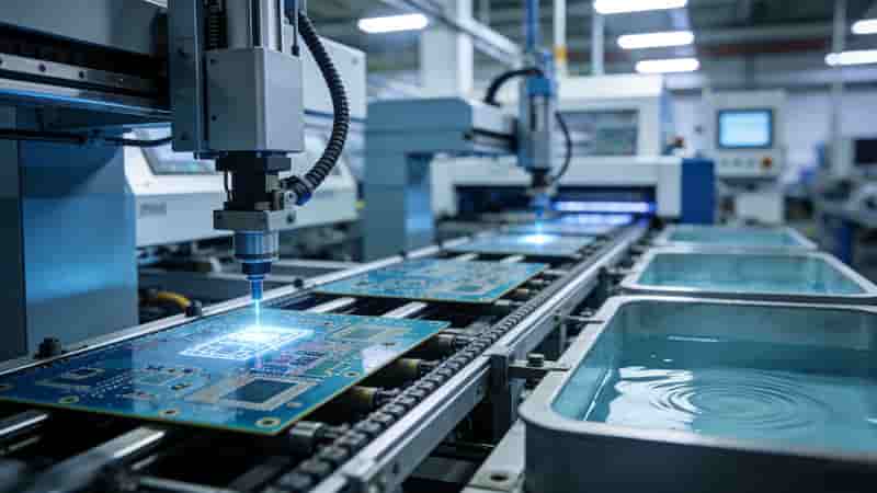
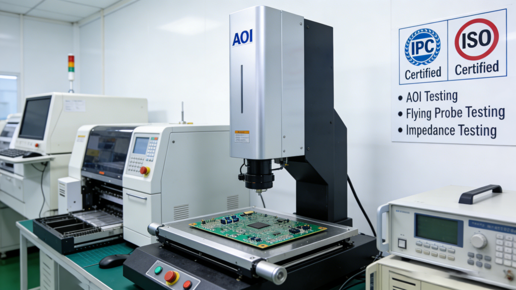
Automated Optical Inspection (AOI) verifies each inner layer for opens, shorts, and line-width compliance before lamination. Defective panels are rejected early to avoid quality loss.
Multilayer Lamination & Stack-Up
Precision stacking uses prepreg and copper foil bonded under controlled heat (170–180°C) and pressure. This step creates a rigid, stable multilayer structure critical for high‑reliability applications.
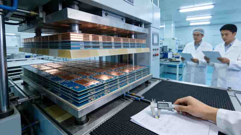
Registration accuracy ensures layer alignment, preventing signal interference and structural failure in industrial and high‑speed designs.
CNC Drilling & Desmear Treatment
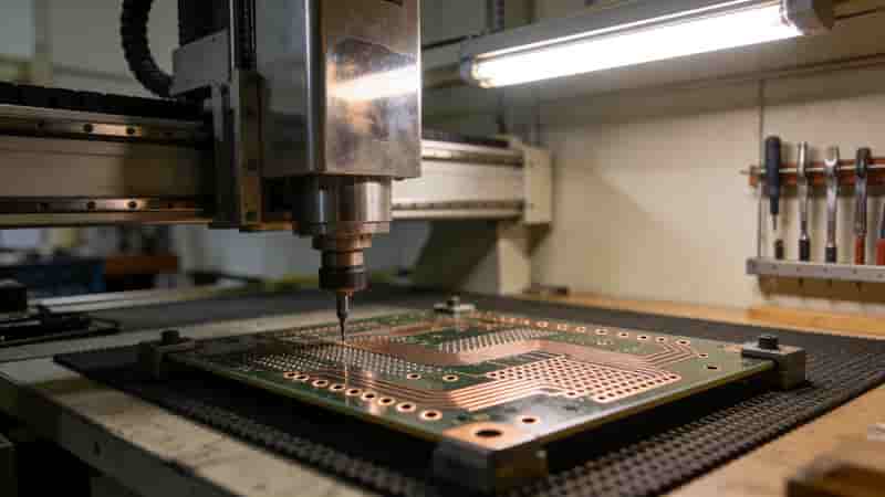
CNC drilling creates vias and through-holes with 0.1 mm precision. Desmear removes resin residue from hole walls to improve plating adhesion and long‑term reliability.
Mechanical drilling supports standard holes; laser drilling enables microvias for HDI PCBs used in compact, high‑performance devices.
Plated Through-Hole (PTH) & Copper Plating
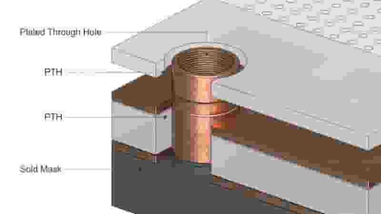
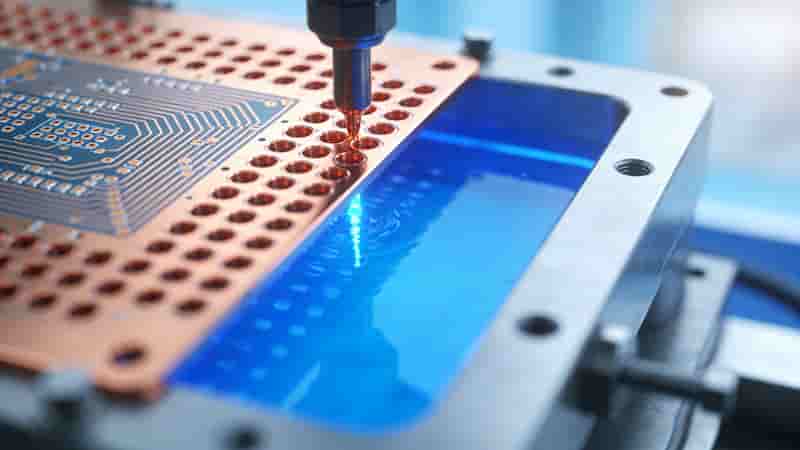
Electroless copper deposition followed by electrolytic plating forms conductive barrels. This step establishes reliable interlayer connections essential in the PCB fabrication process.
Strict thickness control ensures consistent conductivity and thermal stability for industrial and export‑grade PCBs.
Outer Layer Imaging & Final Etching
Outer layers follow imaging, plating, and etching to form finished circuitry. Tin plating acts as an etch resist; final stripping reveals clean, precise traces.
Secondary AOI confirms trace integrity, pad geometry, and isolation before protective coatings.
Solder Mask, Silkscreen & Surface Finish
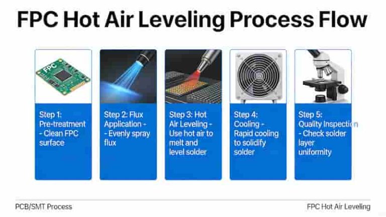
Liquid photo‑imageable solder mask protects circuits from oxidation and shorts. Silkscreen adds component labels for assembly clarity. Surface finish preserves solderability and pad integrity.
Surface Finish Comparison for Industrial PCB Export
| Finish | Advantages | Best For |
|---|---|---|
| ENIG | Flat, long shelf life, fine‑pitch friendly | BGA, high‑reliability, medical/industrial |
| HASL Lead-Free | Low cost, robust solderability | General industrial, through‑hole |
| OSP | Eco-friendly, flat, cost-effective | High-volume SMT, fast assembly |
| Immersion Silver | Excellent solderability, RF-friendly | High-frequency, communications |
Profiling, Electrical Test & Final Packaging
Boards are routed to shape, deburred, and inspected dimensionally. 100% electrical testing verifies continuity and isolation. Final cleaning and ESD packaging ensure safe global delivery.
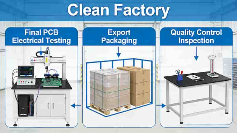
Certificates of conformance (COC), test reports, and material lot records are included for full traceability required by international buyers.
Conclusion
A controlled, repeatable PCB fabrication process is the foundation of reliable, export‑ready printed circuit boards. From DFM to final test, every step ensures performance, consistency, and compliance for industrial, automotive, and high‑tech applications worldwide.
Get Your Custom PCB Quote Today
Send Gerber files, layer count, quantity, and target lead time for a fast, detailed quotation. We support global export with full documentation and quality assurance.
Request PCB Quote
Contact Engineering Team
What Are Tented Vias? A Complete PCB Design Guide
Ball Grid Array (BGA) PCB Manufacturing & Assembly Services
High Tg PCB Materials: A Comprehensive Guide to High-Temperature Performance and Applications
Rigid PCB vs Flex PCB: Key Differences, Applications & Selection Guide
16 Key Factors Affecting Flexible PCB Costs in 2025