Learn professional flex PCB soldering techniques, temperature control, defect prevention, and step-by-step processes to ensure reliable, long-lasting assemblies for industrial and electronic applications.
Why Flex PCB Soldering Is Different From Rigid PCBs
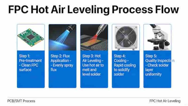
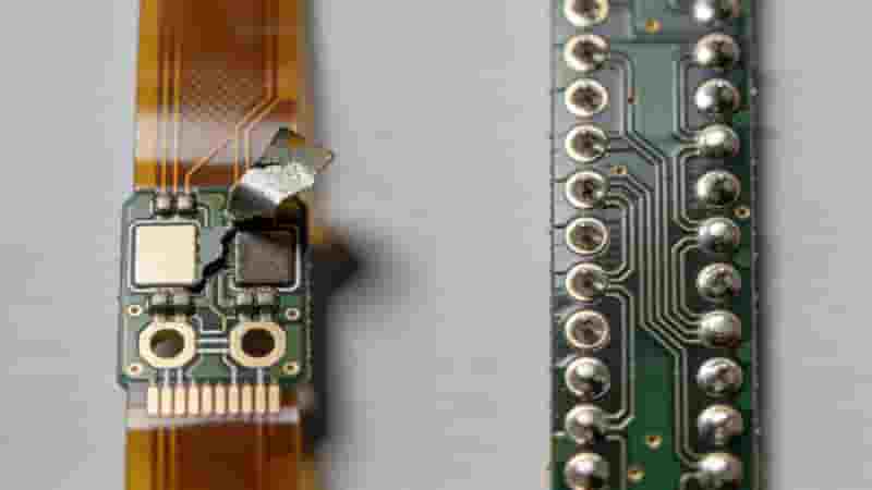
Flex PCBs use thin polyimide substrates that are highly sensitive to heat and mechanical stress. While basic solder principles match rigid boards, flex PCB soldering demands strict thermal control, special fixturing, and adjusted process parameters.
Improper soldering causes delamination, blistering, pad lifting, or permanent damage. Unlike standard PCBs, flex PCB materials cannot withstand high temperatures or prolonged heat exposure.
9 Professional Guidelines for Soldering on Flexible PCB
1. Use Correct Temperature Profiles
Never use standard rigid PCB temperature settings for flex PCB soldering. Typical single-edge flex joints require 330°C – 400°C. Always use the lowest effective temperature to prevent substrate damage.
2. Strict Heat Control During Assembly
Thin flex PCB construction requires effective heat dissipation. Use high surface-area components and compact layouts to shorten thermal paths and avoid heat buildup during flex PCB soldering.
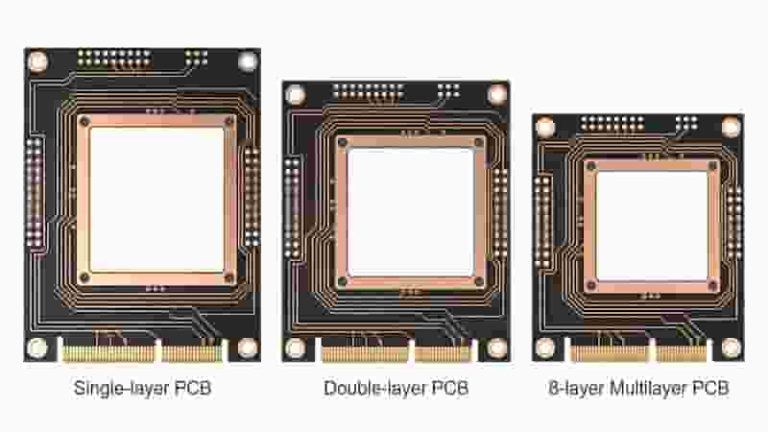
3. Avoid Layer Stacking & I-Beam Effect
Stacking conductors increases thickness and creates stress. Spread signal and return lines to reduce EMI effects while preserving flex PCB flexibility during soldering.
4. Remove Surface Residues
Use a flux pen to clean oxides, improve wetting, and prevent copper oxidation. Proper flux ensures strong, reliable joints in every flex PCB soldering job.
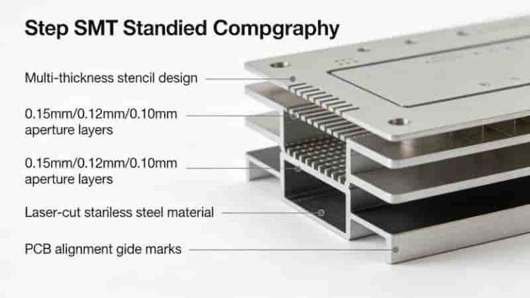
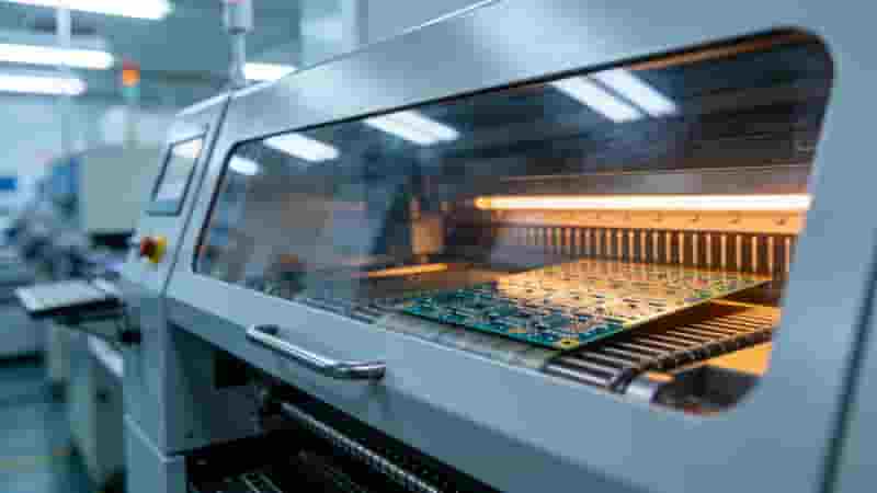
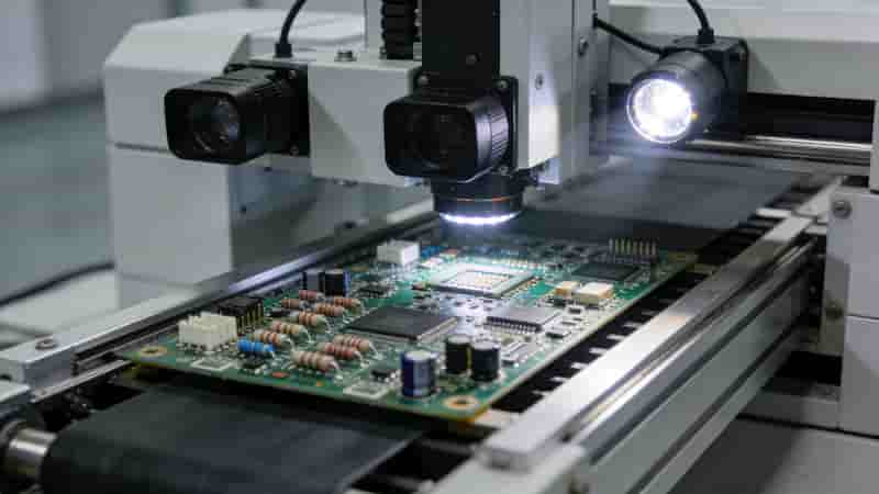
5. Precise Solder Paste Printing
Solder paste printing is critical for SMT flex PCB soldering. Use calibrated SMT stencils to ensure accurate paste volume and perfect pad alignment.
6. Soldering SMT Components
Clean pads with flux → apply solder paste → place components → solder with controlled heat. This sequence ensures stable flex PCB component attachment.
7. Prevent Bending During Soldering
Reinforce the flex PCB back with tape or transparent film to eliminate edge stress and avoid deformation while soldering components.
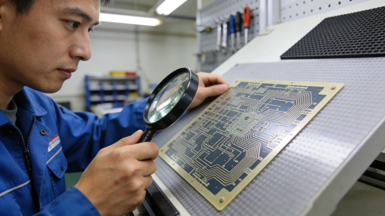
8. Clean Flux Residues Properly
Remove non-no-clean flux residues to avoid corrosion. Failure to clean flex PCB assemblies leads to long-term reliability risks.
9. Allow Tolerance for Stiffeners & Coverlay
Remove excess adhesive after lamination to simplify flex PCB soldering. Design stiffeners and coverlayers with sufficient dimensional tolerance.
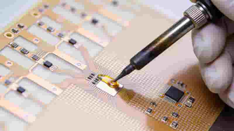
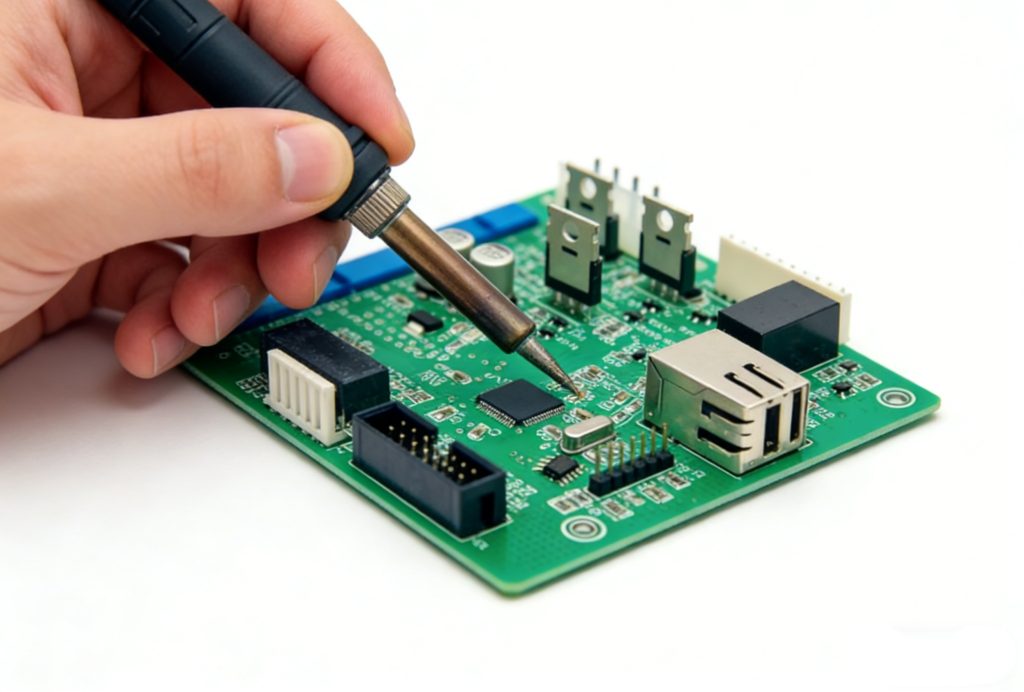
How to Solder Flex PCB by Hand (DIY)
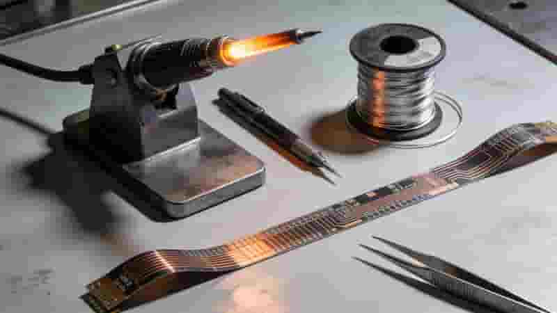
For engineers, makers, and prototypers, manual flex PCB soldering requires these tools:
- Temperature-controlled soldering iron
- Solder paste (Sn43Pb43Bi14 or Sn63Pb37)
- No-clean flux pen
- Hot air pencil or rework station
- Tweezers, fixturing tape, and flat work surface
Common Defects in Flex PCB Soldering & Prevention
| Defect | Cause | Prevention |
|---|---|---|
| Delamination | Excess heat | Lower temp, shorten heat time |
| Pad Lifting | Stress or high heat | Fixture flex PCB properly |
| Cold Joints | Insufficient heat/flux | Use correct flux and temp |
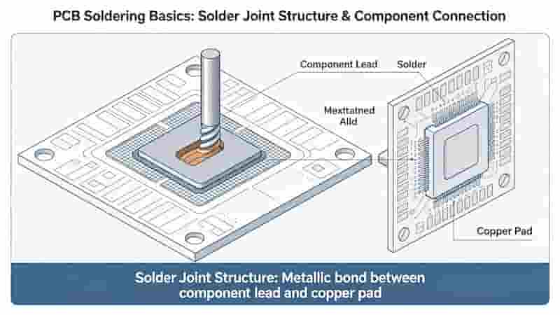
Conclusion
Flex PCB soldering requires specialized processes different from rigid PCB assembly. By following correct temperatures, heat management, fixturing, and cleaning steps, you can achieve high-quality, reliable flex PCB assemblies.
Mastering these techniques reduces failures, improves performance, and extends the service life of flexible circuits in consumer, industrial, and medical electronics.
Need Professional Flex PCB Soldering & Assembly?
We provide reliable flex PCB manufacturing, prototyping, and SMT assembly for global buyers. Get expert support and competitive pricing today.
Request a Quote | Ask Technical Questions
How to Choose a Reliable PCB Manufacturer in Europe: Complete Guide for Industrial Buyers
What is a Pad in PCB Design?
How to Solder on PCB: Essential Techniques and Best Practices for Reliable Assembly
Surface Mount Technology (SMT) PCB Assembly Service
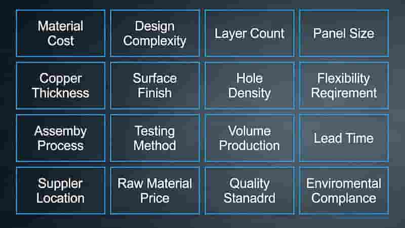
16 Key Factors Affecting Flexible PCB Costs in 2025