|

Free Software for PCB Design for Manufacturing and DFM Analysis

How to use PCB DFM analysis step by step

Use professional PCB DFM analysis software to eliminate manufacturing risks, lower prototype costs, and speed up mass production for global electronics projects.

What is PCB DFM Software

PCB Design and PCB Manufacturing are two separate but closely linked systems. Design data cannot be directly used for production; it requires conversion to CAM (Computer-Aided Manufacturing) data. Without proper analysis, design flaws lead to production failures, delays, and extra costs.

A DFM (Design For Manufacturing) tool checks designs from a production perspective, identifies risks early, and bridges the gap between design and manufacturing teams.
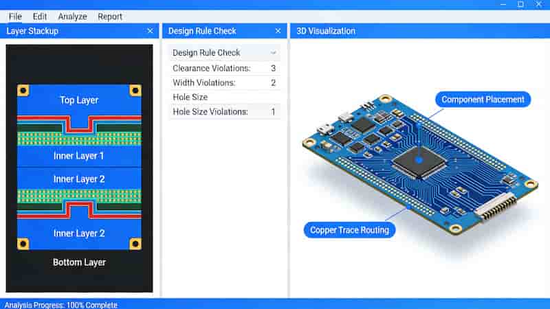
PCB DFM analysis software interface for design verification

Core Functions of Free DFM Tools

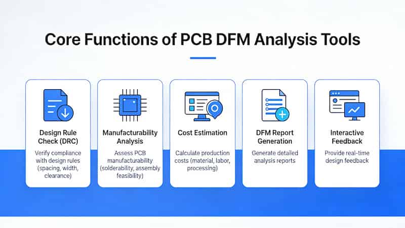
Free PCB DFM software provides essential checks without high costs. Key functions include:

  • Import Altium, Protel, PADS, Allegro, Gerber, ODB++ files
  • One-click automatic manufacturability analysis
  • 23+ critical design rule checks
  • Visual defect location and repair suggestions
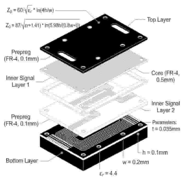
  • Automatic PCB stackup and impedance calculation
  • Component parameter verification
Core functions of PCB DFM analysis tools

Best Free DFM Software Options

Among available free tools, HuaQiu DFM stands out as a reliable solution for engineers and manufacturers. It is lightweight, easy to use, and supports both desktop and online access.

This tool helps users detect design issues before production, improve quality, shorten development cycles, and reduce overall costs.
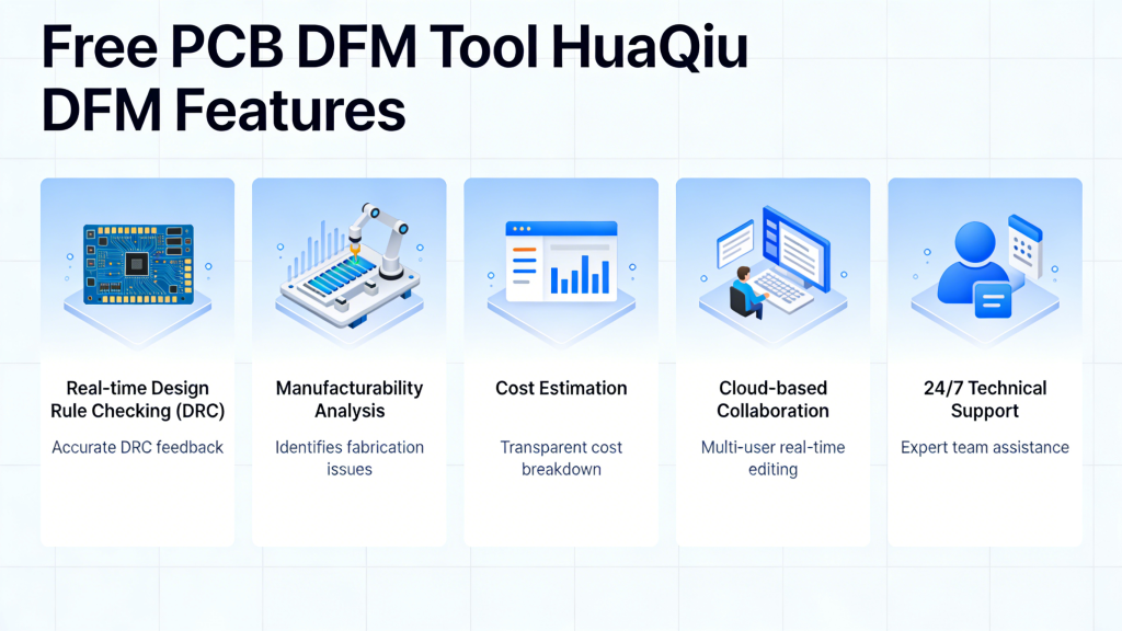
Free PCB DFM tool HuaQiu DFM features

DFM Tool Comparison

FeatureFree DFM SoftwareProfessional CAM Software
CostFreePaid, high license fees
Learning CurveEasy, fast startupSteep, long training
Designer FocusYes, DFM checks optimizedFor production engineers
File SupportAll major EDA formatsLimited design formats

How to Use DFM Software Effectively

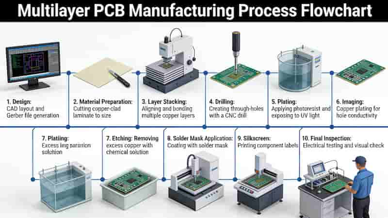
Follow these steps to maximize PCB DFM analysis value:

  1. Import your design files (Gerber, ODB++, or native EDA files)
  2. Run automatic manufacturability inspection
  3. Review error locations and improvement suggestions
  4. Adjust design based on production capabilities
  5. Export optimized files for manufacturing
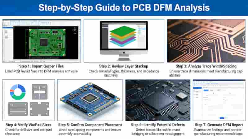
How to use PCB DFM analysis step by step

Benefits for PCB Design & Manufacturing

Using free DFM software brings clear advantages:

  • Reduce PCB prototype cost and rework
  • Shorten lead time from design to mass production
  • Improve PCB reliability and yield rate
  • Minimize communication errors between teams
  • Support consistent quality for global exports
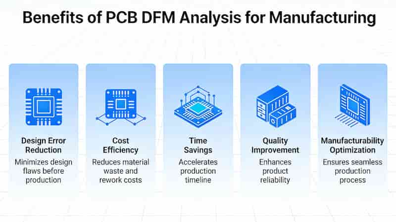
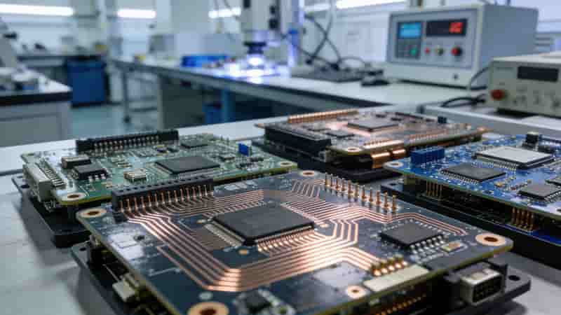
Benefits of PCB DFM analysis for manufacturing

Summary

A reliable free PCB DFM analysis tool is essential for modern PCB design and manufacturing. It reduces risks, lowers costs, speeds up time-to-market, and ensures your boards meet international quality standards.

We provide full PCB manufacturing and assembly support alongside professional DFM guidance for global buyers.

Get Your PCB Project Started

Contact us for PCB fabrication, assembly, or DFM support

Free quote, Fast lead time, Global export support

Inquire Now
4 Layer and 6 Layer Multilayer Flex PCB Stack Up Design

Multilayer Flexible PCB Manufacturer | Custom 4–16 Layer Flex Circuits

Posted on
0 Comments
Lightweight, high‑density multilayer flexible PCB for compact, reliable electronics in consumer, automotive, medical, and industrial applications. Up to 16‑layer flex and rigid‑flex PCB manufacturing with tight tolerances and controlled impedance. 10+ years flex PCB experience in China 1,000,000+ flex circuits shipped per year Quick‑turn prototypes & volume production for multilayer flexible PCB Multilayer Flex PCB…
Flexible PCB materials polyimide PET RA copper ED copper

Flexible PCB: Full Guide to Materials, Design & Applications

Posted on
0 Comments
Flexible PCB (FPC/flex circuit) is a thin, bendable printed circuit that fits 3D spaces. This engineering guide covers materials, design rules, manufacturing, types, reliability & industrial uses for global buyers. Modern electronics demand thinner, lighter, higher-density interconnects. Flexible PCB (also called FPC or flex circuit) has become a core technology enabling miniaturization and 3D packaging….
FR-4 PCB 2025 industry standard material for electronics

Why Choose FR-4 as Your PCB Material in 2025? The Definitive Guide

Posted on
0 Comments
In 2025, FR-4 PCB remains the global leading material for rigid printed circuit boards. It delivers the best balance of electrical performance, mechanical strength, thermal stability, flame resistance, cost efficiency, and mass production compatibility. This guide explains why global engineers and buyers choose FR‑4 for industrial, automotive, IoT, 5G, and EV applications. What Is FR‑4…
Heat Resistant PCB Structure High-Temperature Circuit Board

Heat Resistant Circuit Boards: High-Temperature PCB Solutions for Industrial & Automotive Applications

Posted on
0 Comments
Heat resistant circuit boards are engineered to maintain stability, reliability, and electrical performance in extreme thermal environments. We specialize in high-temperature PCBs, IMS PCBs, and high-Tg FR4 boards for automotive, aerospace, industrial power, and LED systems. Request a Quote What Are Heat Resistant Circuit Boards? Heat resistant circuit boards are printed circuit boards designed to…
Rigid PCB Prototype FR-4 Industrial Circuit Board

Learn the Essential Requirements for PCB Prototype Manufacturing in 2025

Posted on
0 Comments
Summary: Master critical standards for PCB prototype manufacturing including file formats, design rules, layer stackup, and documentation. Optimize your prototyping workflow with expert best practices to achieve high-quality, cost-effective, and on-time PCB prototypes for industrial and engineering applications. Prototype PCB Fabrication PCB prototyping is a crucial step in the electronics design process, enabling designers to…
PCB and PCBA applications in industrial control and automotive electronics

What Is the Difference Between PCB and PCBA? A Complete Guide for Industrial Buyers

Posted on
0 Comments
This article clearly defines PCB and PCBA, explains core technical differences, manufacturing processes, functionality, cost, and application scenarios to help global engineers and purchasers make accurate procurement decisions. 1. Definitions of PCB and PCBA PCB (Printed Circuit Board) is the bare printed circuit board without electronic components. It provides mechanical support and electrical connection paths…

FAQs About PCB DFM Analysis Software & Application

A: It inspects PCB design from manufacturing perspective, finds hidden design defects in advance, gives modification advice to avoid post-production rework and extra expense.

A: Compatible with Gerber, ODB++ and native files from Altium, PADS, Protel, Allegro and other mainstream EDA design software.

A: Free DFM is zero cost, easy operation for design engineers; professional CAM needs expensive authorization and complicated training focusing on factory production data processing.

A: Import design files → run automatic inspection → check error positions & optimization tips → revise PCB layout → export corrected documents for production.

A: Cut prototype rework cost, shorten project lead time, raise finished PCB yield and reduce communication deviation between designer and manufacturer.

A: No, DFM only fixes design flaws upfront; CAM is still required for subsequent factory production data conversion and process setup.

A: Trace width/spacing, via size, annular ring, pad clearance, stackup impedance calculation and component layout manufacturability verification.

A: Yes, mature free DFM tools follow industrial standards and are widely adopted by global engineers for pre-production design verification.

Similar Posts