PCB Design Software Free Download
This is a comparison of several PCB design tools that meet the following criteria:
- The software is actively maintained and updated.
- A free version is available.
- The free version has no time limit.
- It supports schematic capture and PCB layout design, and can generate files for PCB manufacturing.
1. PartSim
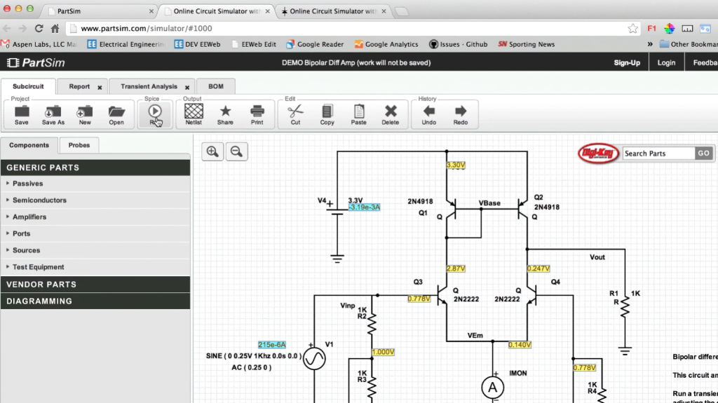
PartSim is a free, user-friendly online circuit simulator featuring a full SPICE simulation engine, web-based schematic capture, a graphical waveform viewer, and direct Digi‑Key integration—all accessible via your web browser. It also includes an integrated Bill‑of‑Materials (BOM) manager that lets you assign Digi‑Key part numbers to your designs.
Features:
- SPICE Simulator
- AC / DC / Transient Simulations
- Graphical Waveform Viewer
Category: Free Online PCB Design Software
2. Scheme-it
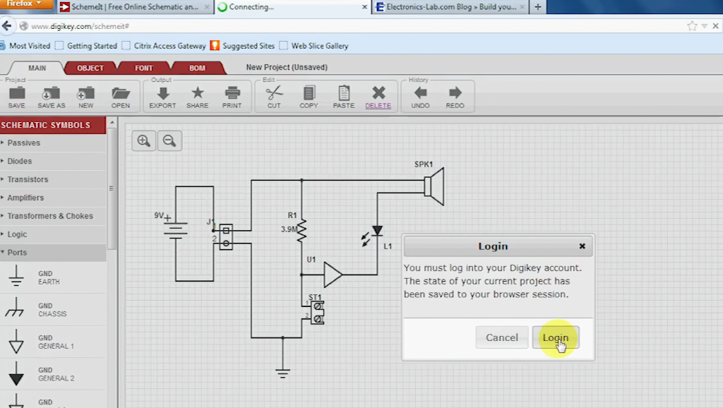
This tool comes with a complete electronic symbol library and seamless integration with the Digi-Key compoScheme-it is a free online schematic and diagramming tool for designing and sharing electronic circuit diagrams. It includes a comprehensive electronic symbol library and an integrated Digi-Key component catalog for diverse circuit designs, plus a built-in BOM manager to track parts. Completed schematics can be exported to image files or shared via email. Scheme-it runs natively on all major web browsers without plugins. Only registered users can save and share designs.
Features:
- Diagram at Block, Icon, System, or Schematic levels
- 700+ generic symbols, plus custom symbol creation
- Access to 4 million+ components via Digi-Key Catalog integration
- Keep designs private, make them public, share via link, or embed in web pages, blogs, or emails
- Rapid design iteration via BOM import capability
- Integrated BOM management and component quoting
- Export schematics to PDF or PNG files
- Direct access to Digi-Key Technical Support for component selection assistance
Type: Online Free PCB Design Software
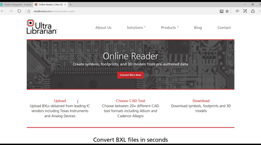
3. Ultra Librarian
Features
- Automated and manual footprint, symbol and 3D model creation
- Pre-built library parts exportable to most CAD formats
- Full integrated verification system
- Component database system
- Footprint database system
- Component intelligence
Notes
- Free Download
- Free Online PCB CAD Library
- World’s Largest PCB CAD Library
- Vendor-neutral data for ECAD design, simulation and 3D modeling
Accelerated Designs provides vendor-neutral data for ECAD design, simulation and 3D modeling to component manufacturers and engineers. Its flagship Ultra Librarian creates and exports vendor-neutral ECAD data compatible with 22+ CAD tools. Build components accurately once and export to your preferred CAD tools. It offers the industry’s largest pre-built ECAD library: 7.2M+ parts from 400+ manufacturers, 82% with 3D STEP models. Flexible Part Packs and yearly subscriptions are available.
Accelerated Designs provides the fastest and most accurate PCB library management tool. It is a customizable one-stop source for CAD, simulation, 3D modeling and engineering data to meet company and client needs.
With Ultra Librarian, you can:
Design: Focus on creating revolutionary electronics.
Search: Quickly find verified parts from top manufacturers in our expanding database.
Download: Free unlimited access to schematic symbols, PCB footprints and 3D STEP models in native CAD formats.
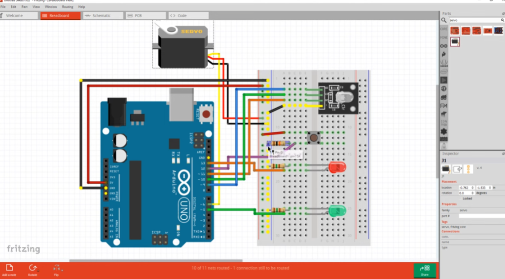
4. Autodesk Circuits
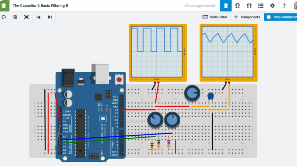
Autodesk Circuits provides free, easy-to-use online tools to turn ideas into reality. Beginners can start with basic experiments in the Electronics Lab or Circuit Scribe, while experienced users can directly access PCB design.
- Simulate and program Arduino and breadboard components
- Build complex circuits using standard modules
- Create and test circuits, then export to PCB design software
Notes: Web-based app; free version makes designs public.
Output Gerbers: Yes
5. CircuitMaker
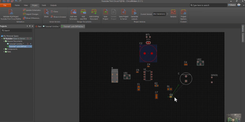
Altium’s CircuitMaker delivers trusted PCB design technology used worldwide.
It is the best free schematic and PCB design tool for the open-source hardware community.
CircuitMaker is more than free EDA software from Altium — it is a collaborative community of creators and design content, working together to develop circuits and electronics.
To turn ideas into real products without limitations, CircuitMaker provides full-featured tools for high-quality schematics and PCBs, with no artificial restrictions on layer count or board area.
It is a vibrant community of open-source designers, makers, hobbyists, students and professionals building innovative products daily.
Output Gerbers: Yes
Recommended PCB Manufacturing Services
6. SoloPCB Design
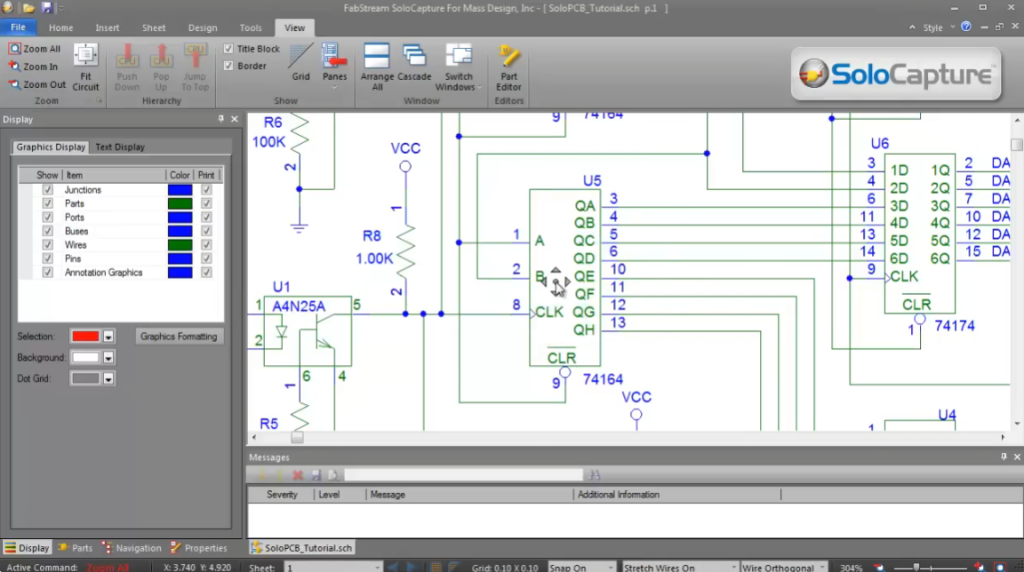
SoloPCB Design features schematic capture, PCB layout, and integrated auto‑routing. It supports designs from single‑sided PCBs to high‑layer‑count advanced circuits, with full, unrestricted functionality.
Intuitive and easy to learn, the software offers flexible workflows: schematic‑driven design via SoloCapture’s hierarchical editor, or direct PCB layout without a schematic.
We partner with leading global PCB manufacturers; their design rules are built into the software, and manufacturing data transfer is automated for fast, defect‑free production.
SoloPCB provides professional features normally found only in commercial EDA tools.
Notes: Usable only with licensed manufacturers
Gerber Output: Yes
7. MultiSIM BLUE 14
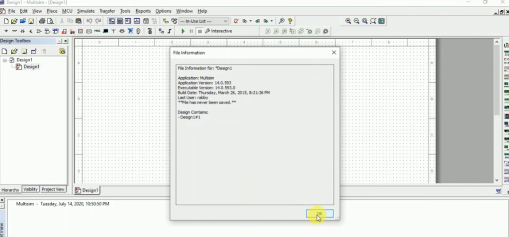
NI Multisim 14 delivers a best-in-class engineering design experience for classrooms and labs, supporting SPICE simulation and prototype measurements. As a robust virtual electronics workbench, it is the preferred tool for students and engineers to explore, develop, and implement new circuit designs and electronic innovations.
System Requirements for MultiSIM BLUE
- Platform: Windows
- Processor: Pentium 4/M class or equivalent
- Memory: 512 MB RAM (minimum 256 MB)
- Hard Disk: 2 GB free space
- Graphics: OpenGL-capable 3D card recommended; minimum SVGA 800×600, preferred 1024×768 or higher
Supported Windows Versions
- Windows 10 (32/64-bit)
- Windows 7 SP1 (32/64-bit)
- Windows Server 2008 R2 (64-bit)
- Windows 8.1 (32/64-bit)
- Windows Server 2012 R2 (64-bit)
8. Target 3001! PCB-POOL Edition
Use TARGET 3001! PCB-POOL® Edition – completely free for PCB-POOL® customers, with full design capabilities.
TARGET 3001! PCB-POOL® Edition
Online ordering integration
- All functions (PCB & front panel) enabled – equivalent to the Professional edition
- Production data restricted to PCB-POOL® / PANEL-POOL® manufacturing only
- Project files (.T3000) are not compatible with standard TARGET editions (.T3001)
- Unlimited pins and pads for PCB design
- Unlimited tool moves for front panel design
- Up to 100 copper layers
- Up to 100 simulatable signals
- Maximum board size: 78″ × 78″
- Unlimited access to the component database
- Full‑scale PCB printing supported
- Built‑in PCB-POOL® & PANEL-POOL® price calculator
- Assembly tool with price calculator
- MID design support
- PCB Layout
- PCB Simulation
- Schematic Capture
- Auto‑Placer
- Auto‑Router
- EMC Analysis
- Integrated assembly cost calculation
9. PCBWeb
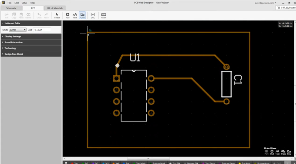
PCBWeb is a free online CAD application for designing and manufacturing electronics hardware, fully integrated with the Digi‑Key component catalog and BOM manager.
System Requirements:
Graphics: DirectX 11 compatible adapter with MSAA support
OS: Windows 7 (32/64-bit), Windows 8, Windows 8.1, Windows 10
10. Osmond PCB

Printed Circuit Board Design for Macintosh – Design Without Restrictions
Osmond PCB for Macintosh delivers powerful, flexible PCB design for both new and experienced users—free of artificial limits. Design boards of any size, shape, and layer count with exceptional precision: 10 nanometers (0.00001 mm) spatial resolution. Place components anywhere in any orientation, route traces of any width along any path and angle.
Osmond includes integrated design rule checking (DRC) to verify correctness and compliance with your specifications.
Finished designs export standard Gerber (RS‑274X) and Excellon drill files for professional fabrication. You may also define custom panels with multiple designs. For DIY fabrication, Osmond generates PostScript output that prints directly onto transparencies for etching.
Key Features
- Free (donation‑based)
- Any board size / shape
- Unlimited layers
- Supports through‑hole and SMT components
- Design rule checking (DRC)
- Metric & Imperial units
- Ground planes & copper flooding
- PDF background import
- Gerber & Excellon drill output
- PostScript & DXF export
- Lua scripting support
Limitations
Maximum pins: 700
11. EasyEDA
EasyEDA offers a free version for everyone.
As a web-based EDA tool suite, it empowers hardware engineers to design, simulate, share (publicly or privately), and collaborate on schematics, simulations, and printed circuit boards. Additional features include BOM generation, Gerber files, pick-and-place files, and documentation exports in PDF, PNG, and SVG formats.
EasyEDA supports schematic creation and editing, mixed analog/digital SPICE simulation, PCB layout design and editing, plus optional PCB manufacturing services.
Supported Platforms
- Windows: Windows 7 and above (32/64-bit)
- Linux
- Mac
- Available as both online editor and desktop client
12. Fritzing
Fritzing is an open-source hardware initiative that makes electronics accessible as a creative material for everyone. We provide a software tool, community platform, and services inspired by Processing and Arduino, building a creative ecosystem for documenting prototypes, sharing projects, teaching electronics in classrooms, and designing professional PCBs for manufacturing.
Installing Fritzing
Please ensure your system meets the following requirements:
- Windows: Windows 10 (Windows 7 also reported compatible)
- Mac: macOS 10.14 or newer (10.13 may work; 10.15 untested)
- Linux: Recent distribution with libc ≥ 2.6
- Download the appropriate Fritzing package for your system.
- Unzip the Fritzing folder to a convenient location on your hard drive.
- Optionally create a shortcut to the Fritzing application for easy access.
Launching Fritzing
Linux: Double-click Fritzing, or run ./Fritzing in the terminal
Windows: Double-click fritzing.exe
Mac: Double-click the Fritzing app
13. Target 3001! discover

TARGET 3001! is a German CAD/CAE software for PCB design developed by IBF.
It integrates schematic capture, simulation, PCB layout, autorouter, 3D view, and front panel design in a single unified interface. Built-in price calculators and direct ordering functions for PCBs and front panels are also included.
The ELECTRA autorouter comes embedded in all editions, supporting up to 250 pins. All project data is stored in one central file, eliminating conversion issues and version conflicts between schematic and layout. TARGET 3001! generates industry-standard manufacturing data for professional production.
TARGET 3001! V20 DISCOVER
- Up to 250 pins/pads
- 2 copper layers
- Board area up to 2.0m × 2.0m
- All functions fully active*
- No time limit, no license codes required
- Simply download and start designing
Limitations: 2 copper layers; max 250 pins
14. PCB Artist
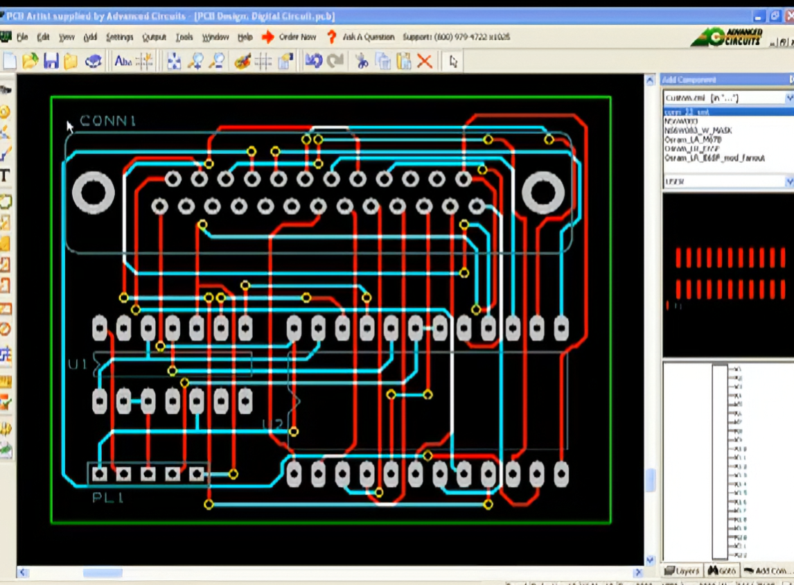
Free Download
PCB Artist is a user-friendly, fully integrated schematic capture and free PCB layout software designed for simplicity. Download and install it at no cost, and start designing your PCBs right away. The software is specially developed to require no formal training or prior PCB layout experience.
Once your design is finished, you can save files locally or upload them directly to us for production. Tutorials are available for quick setup, and Gerber files are included with your order.
Operating Systems
- Windows 10
- Windows 8
- Windows Vista
- Windows 7
- Windows XP
Limitations
Maximum layers: 10
15. PCB123
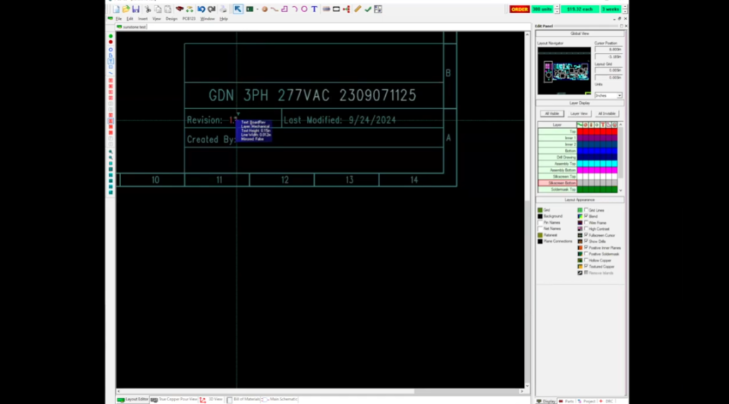
ONE OF THE FIRST FREE-TO-USE PCB DESIGN TOOLS AVAILABLE.
PCB123 is a full-featured PCB design tool for users of all skill levels. Launched as a free solution in 2002, it continues to use a risk-sharing business model: we only get paid when you successfully complete your PCB design. Our dedicated technical support team consists of industry professionals ready to assist you and ensure your design success.
Experience easy-to-use, professional-grade PCB CAD software that is completely free and fully supported.
Available only for Windows environments.
Limitations:
- For use with Sunstone manufacturing only
- Maximum 6 layers
16. Pad2Pad
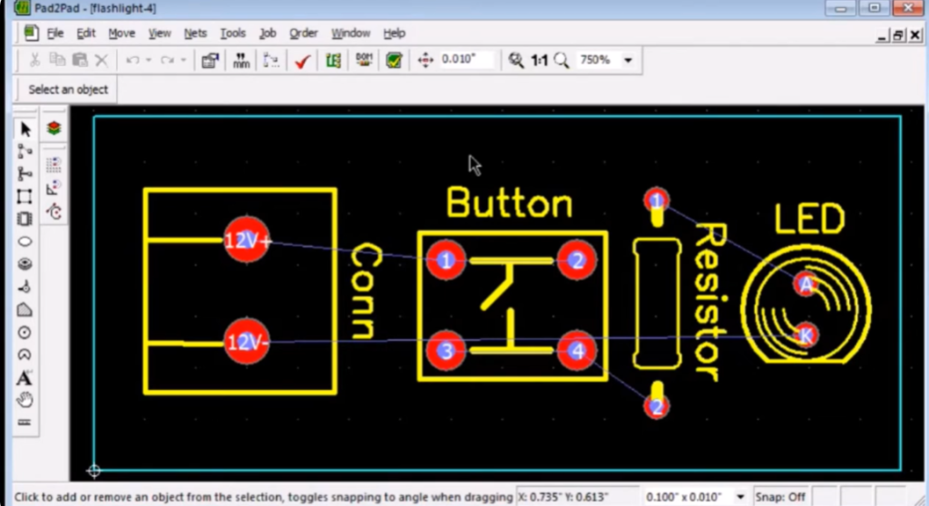
The free Pad2Pad CAD PCB layout software includes intuitive yet powerful features for your board design:
- Multiple pad types: single-layer, multi-layer, vias, rectangular, round
- Various trace widths
- Standard and custom footprints
- Design Rule Check (DRC)
- Full control over PCB views and layers
- Move, rotate, and delete objects
- Grid and angle snap
- Undo / Redo
- Geometric shapes: lines, arcs, circles, polygons
- Customizable text (size and font)
- Ground plane wizard
- Logical net connections via dialog or GUI
- Auto-generate nets from traces
- Auto-routing
- Component assembly support
- Instant pricing
- Online ordering
Limitations:
For use only with Pad2Pad PCB manufacturing
Maximum 4 layers
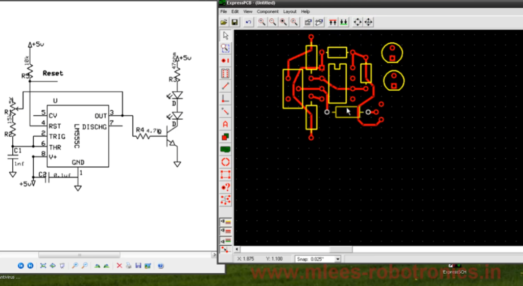
17. ExpressPCB

Laying out PCBs is simple, even for first‑time users. Both ExpressPCB tools are free to use and easy to learn.
ExpressPCB Classic
- 2–4 layers
- Top silkscreen layer
- Schematic-to-layout linking
- Integrated manufacturing support
ExpressPCB Plus
- 2–6 layers
- Top & bottom silkscreens
- Copy & paste between designs
18. CometCAD
CometCAD is a design tool for creating circuit schematics and printed circuit boards (PCBs).
Built for Windows and offered under a free‑use license, CometCAD organizes PCB design into three stages: symbols, circuits, and layout.
CometCAD supports Windows 2000, XP, Vista, and 7.
Circuit Editor
- Multi‑sheet schematics
- Max sheet size: 2 m × 2 m
- 90° symbol rotation steps
- Netlist transfer to PCB (forward annotation)
- Part list export
- SPICE netlist output
PCB Layout Editor
Rectangular multi‑PCB panel creation
- 1 or 2 copper layers
- Internal resolution: 1 micrometer
- Max PCB size and pin count vary by license level
- Copper planes and design rule checking
- Adjustable trace width between corners
- 90° component rotation steps
- CAM output: Gerber, drill, pick‑and‑place files
- Polygon‑shaped PCB borders
- Support for milled gaps/cuts and round holes
19. PCB Elegance
PCB Elegance is a Windows-based PCB design suite featuring schematic capture, board layout, and manufacturing file generation. First released in 1998 as proprietary software, it became open-source under the GPL license in 2012.
Features
- Gerber file output support
- Free and open-source
- Easy to learn with a logical, modern, and consistent user interface
- Smooth mouse-controlled zoom and panning
- Handles complex designs: supports 2000+ components and 40,000+ traces (includes a Pentium motherboard as an example)
- Keyboard shortcuts shown beside menu items for learning-on-the-go; fully customizable
- Customizable colors for schematic and layout editors; layout supports two‑tone patterns
- Routing with online DRC, active rats nest, and trace dragging
- Active schematic selection to pick groups of layout components directly from the schematic
- Batch editing of parameters for multiple components
- Fast creation of complex schematic symbols with the built‑in symbol editor
- Pre‑loaded symbol libraries
- Geometry editor with wizards for DIP, SOIC, BGA, and other IC packages
- Context‑sensitive help
20. OrCAD PCB Designer Lite
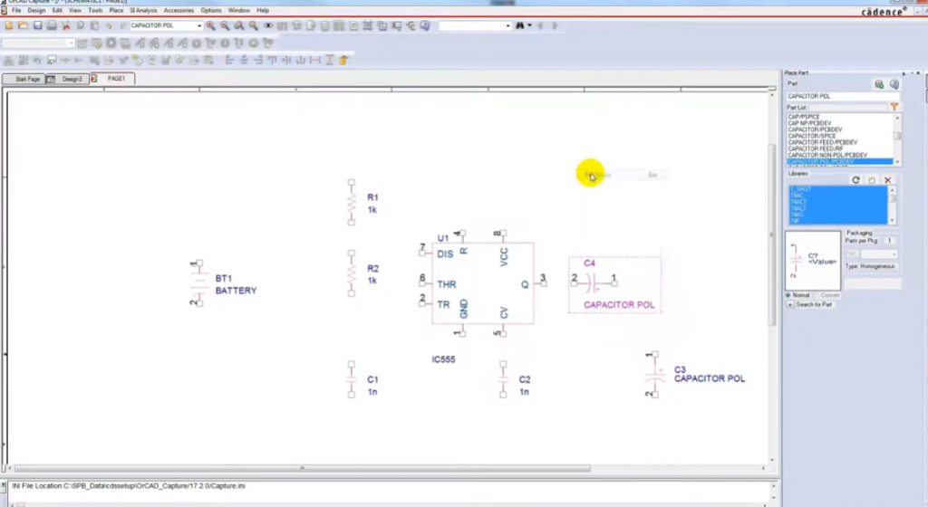
OrCAD PCB Designer Lite is a Cadence solution that helps electrical engineers and layout designers create high-quality printed circuit boards. It delivers a modern, powerful toolset with advanced editing and routing capabilities.
As a Cadence product, OrCAD PCB Designer Lite empowers designers to explore and realize their ideas using intuitive, high‑productivity design technology.
At its core, the OrCAD PCB Editor enables intelligent auto‑routing to reliably connect components while fully preserving your design intent.
21. Layo1
Layo1 PCB Specifications
- Program & help available in multiple languages
- Internal resolution: 0.0001 mm (0.1 micron)
- Max PCB size: 2000 mm × 2000 mm
- Unlimited vectors per design
- Support for documentation layers: silkscreen, solder mask, solder paste, assembly, etc.
- Unlimited track widths (including documentation layers)
- Unlimited pad definitions
- Unlimited via definitions
- Unlimited drill diameters
- Component rotation: 0.001° precision
- Track/pad libraries supported
- Customizable layer colors per design
- Customizable background color
- Customizable drill hole colors
- Unlimited track widths per net
- Min/max track width configurable per net
- Tables for viewing/editing netlist, components, pads, layers, etc.
- Undo/Redo: up to 5 steps
- Online DRC (Design Rule Check)
- Persistent & auto-updating rats nest
- Copper pour support
- Automatic & configurable backup files to separate drive/computer
- Context-sensitive online help
22. CADSTAR Express
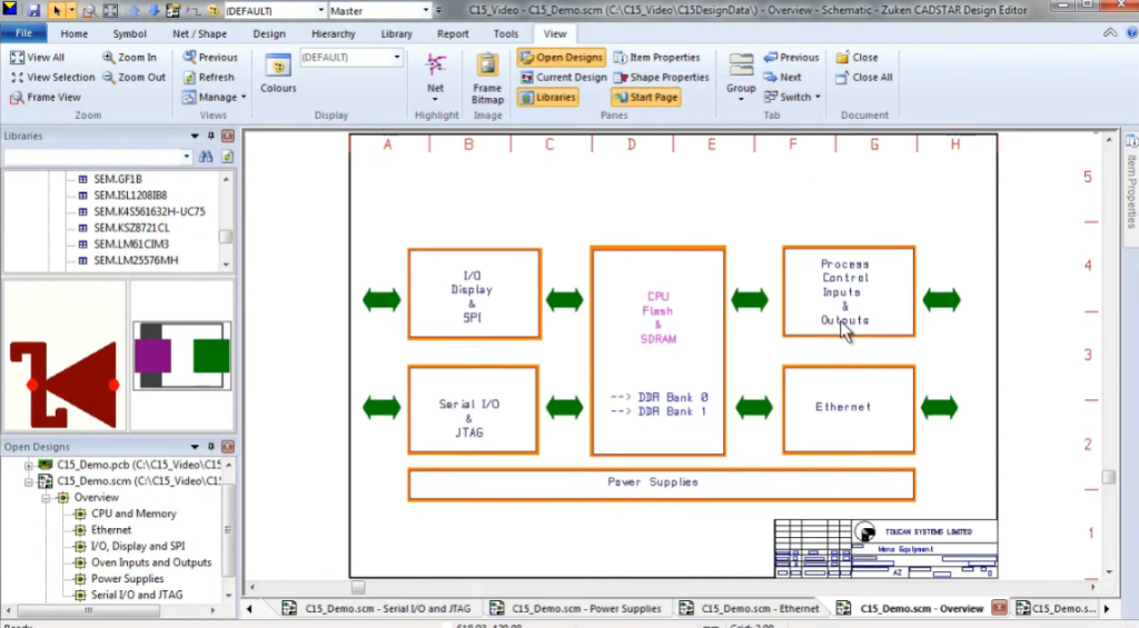
CADSTAR Express offers a fast, user-friendly way to explore the core features of Zuken’s standard PCB design solution. It includes the full functionality of CADSTAR 17.0, with limits of 300 pins and 50 components, plus access to Zuken’s advanced P.R.Editor XR 2000.
CADSTAR Express supports limited viewing of the CADSTAR Online Library (250,000+ parts). A larger sample library with 20,000 parts is available as a separate download.
23. ZenitPCB
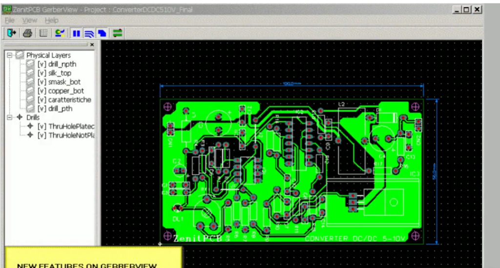
Free PCB Layout for Your Electronic Projects
ZenitPCB Suite is ideal for hobbyists, students, and educators seeking a professional‑grade PCB design tool without expensive licensing.
ZenitCapture Schematic
Intuitive and fast to learn, with a streamlined toolset for quick schematic creation. Schematics define electrical logic and connections using symbolic components and signal wires. Supports multi‑page schematics and generates netlist (ASCII) files for PCB layout transfer.
ZenitPCB Layout
A flexible, user-friendly CAD program for creating professional PCB designs.
Freeware for personal and semi‑professional use, with a limit of 800 pins—perfect for bridging hobby and professional projects.
24. Open Circuit Design
Open Circuit Design offers free PCB layout software with professional-quality output and extensive features. It supports UN*X-based systems, including GNU/Linux, macOS, and Windows via Cygwin.
Originally developed by Thomas Nau (Ulm, Germany), the project is now maintained by Harry Eaton at the Johns Hopkins University Applied Physics Laboratory (Laurel, MD, USA).
PCB 3.0 is a Tcl/Tk-based branch rewritten by Tim Edwards, Paramesh Santanam (MultiGiG, Inc., Scotts Valley, CA) and Nishit Patel (SynApps, Inc., India). It introduces a full Tcl command-line API and a new Tk-based GUI, while preserving the look and feel of the original Xlib version.
Limitations:
- Maximum 8 layers
- Windows version only
25. gEDA
The gEDA project offers a full, GPL‑licensed suite of electronic design automation (EDA) tools for circuit design, schematic capture, simulation, prototyping, and production.
This mature open‑source toolkit includes:
- Schematic capture
- Attribute management
- Bill of Materials (BOM) generation
- Netlisting support for 20+ formats
- Analog & digital simulation
26. FreePCB
FreePCB is a free, open‑source PCB editor for Microsoft Windows, licensed under the GNU General Public License. It is designed to be easy to learn and use, while supporting professional‑quality results. Although it does not include a built‑in autorouter, it can connect to the FreeRoute web‑based autorouter at
Key features:
- 1–16 copper layers
- Board size up to 60” × 60”
- Supports imperial (mils) and metric (mm) units
- Footprint libraries from Ivex Design International, PCB Matrix, and IPC
- Copper fill areas
- Footprint Wizard and Footprint Editor for custom footprints
- Imports & exports PADS‑PCB netlists
- Exports RS‑274X extended Gerber and Excellon drill files
- Design Rule Check (DRC)
27. DesignSpark PCB
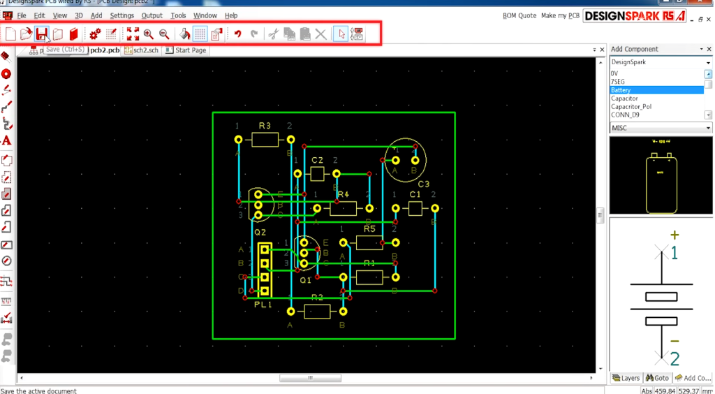
DesignSpark PCB is free to download and use—forever.
It helps teams explore more design possibilities and drive innovation. Powered by a robust engine, this versatile tool supports schematic capture and full PCB board/layout design.
Key Features
- Integrated PCB Part Library
- Seamlessly fits into existing design workflows
- No limits on schematic size
- No restrictions on PCB design complexity
- Create custom libraries or use built‑in libraries
- Flexible file output
- Customizable BOM generation
28. KiCad
KiCad is a free and open-source electronic design automation (EDA) suite for schematic capture and PCB layout, with full Gerber file export. It runs on Windows, Linux, and macOS, and is licensed under the GNU GPL v3.
Originally released in 1992 by Jean‑Pierre Charras, KiCad is now actively developed by the global KiCad Developers Team.
Features
Schematic Capture
- Unlimited design size with no locked features
- Official schematic symbol library
- Built‑in symbol editor
PCB Layout
- Professional PCB design with up to 32 copper layers
- Push‑and‑shove interactive router
- Differential pair routing
- Interactive trace length tuning
3D Viewer
- Toggle layer visibility for detailed review
- Real‑time 3D inspection with pan and rotate
- Multiple rendering modes
29. Eagle
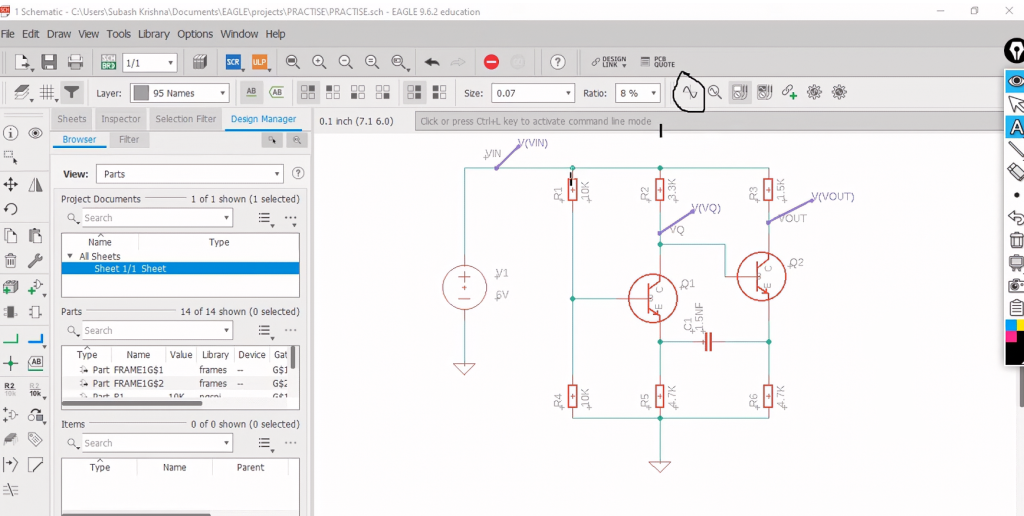
EAGLE is a scriptable electronic design automation (EDA) application featuring schematic capture, PCB layout, auto‑router, and CAM (computer‑aided manufacturing) capabilities. EAGLE stands for Easily Applicable Graphical Layout Editor, developed by CadSoft Computer GmbH and acquired by Autodesk in 2016.
The schematic editor supports multi‑sheet circuit diagrams with component placement and port‑based connectivity.
The PCB layout editor enables back‑annotation to the schematic and auto‑routing that follows schematic net connections.
EAGLE outputs standard Gerber, PostScript, Excellon, and Sieb & Meyer drill files widely accepted by PCB manufacturers.
Features
- Schematic Editor: Create clear, symbolic circuit representations
- Layout Editor: Translate designs into physical PCB boards
- Auto‑router: Automate copper trace routing between components
- Export: Gerber, BOM, and SVG files for sharing and manufacturing
Pros:
- Easy to learn for hobbyists and beginners
- Offers free limited versions
Cons:
- High‑tech designs require more manual calculations and routing compared to premium EDA tools
- Less common in large enterprises with in‑house PCB teams
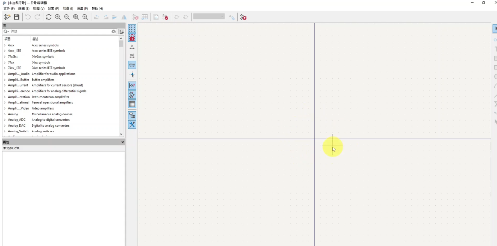
30. Tiny CAD
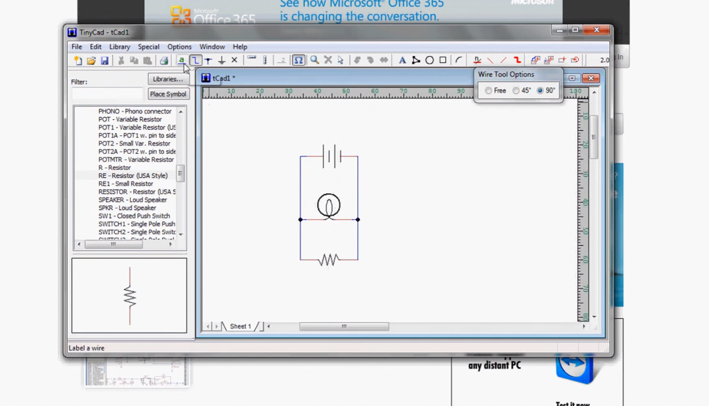
TinyCAD is a straightforward, open-source tool for creating electronic circuit diagrams and basic PCB designs. It is also widely used for drawing single-line diagrams, flowcharts, and presentation graphics.
TinyCAD supports multiple netlist formats for compatibility with PCB layout software, can generate SPICE simulation netlists, and includes symbol libraries. This free PCB design tool also features circuit design error checking.
In addition to printing, you can copy and paste drawings directly into Word documents, or export them as PNG images for online use. It can also serve as a front-end interface for other PCB layout tools.
Features
- Supports standard and custom libraries
- Circuit design error checking
- Print, copy, and save functions
- Multiple output formats for PCB production
System Support
Windows only