We are a professional Metal Core PCB (MCPCB) manufacturer in China, providing fast prototyping, small-batch and mass production of aluminum & copper core PCBs for LED, automotive and power electronics with competitive pricing and full engineering support.
Why Metal Core PCB (MCPCB) for High-Power Designs
High-power electronic designs face critical thermal management challenges that traditional FR4 PCBs cannot solve. Metal Core PCB (MCPCB) with aluminum or copper substrates delivers superior heat dissipation, ensuring stable performance for LED arrays, power converters and automotive electronics.
Poor Thermal Performance of FR4 PCBs
Standard FR4 boards have thermal conductivity of only 0.3 to 0.4 W/mK, trapping heat around high-power components. This causes performance degradation, thermal shutdown and premature failure in lighting, power supplies and automotive systems.
Superior Heat Dissipation with MCPCB
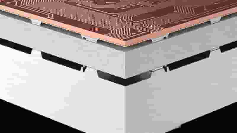
MCPCB uses aluminum or copper cores with thermal conductivity up to 8.0 W/mK, 20 times better than FR4. The metal base acts as an integrated heat sink, rapidly removing heat from components and maintaining low junction temperatures.
Extended Component Lifespan
High temperatures accelerate LED brightness decay and color shift. MCPCB reduces operating temperature by 10 to 30°C, extending LED lifespan to 50000+ hours and lowering maintenance costs.
Simplified Thermal Design
Metal Core PCB integrates heat dissipation into the substrate, reducing or eliminating external heat sinks. This simplifies assembly, cuts BOM cost and saves space for automotive, aerospace and industrial applications.
Enhanced Reliability & Safety
Overheating risks solder joint failure and safety hazards. MCPCB provides stable thermal performance, helping products meet AEC-Q, IEC 60601 and industrial safety standards.
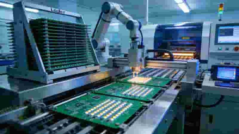
Our MCPCB Manufacturing Service
We focus on fast, reliable Metal Core PCB (MCPCB) solutions for global LED, automotive and power electronics clients. We support rapid prototyping to mass production with consistent quality.
- Fast MCPCB prototyping in 3–5 days with low MOQ (1 piece)
- Aluminum & copper core options for various thermal needs
- Competitive pricing for small-batch and volume orders
- Professional DFM review and thermal design support
MCPCB Production Capabilities
| Parameter | Specifications |
|---|---|
| Metal Base Materials | Aluminum (5052, 6061), Copper |
| Thermal Conductivity | 1.0–3.0 W/mK (Aluminum); Up to 8.0 W/mK (Copper) |
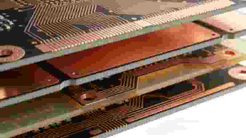
| Layer Count | Single-sided, Double-sided, Multilayer |
| Metal Thickness | 0.8–3.0 mm (custom available) |
| Copper Thickness | 1–6 oz |
| Min. Trace/Space | 3/3 mil |
| Surface Finish | HASL, Lead-free HASL, ENIG, OSP, Immersion Silver/Tin |
| Prototype Lead Time | 3–5 days |
| Mass Production Lead Time | 7–12 days |
MCPCB Key Applications
Metal Core PCB (MCPCB) is widely used in high-power, heat-sensitive equipment requiring excellent thermal management.
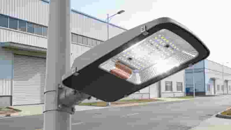
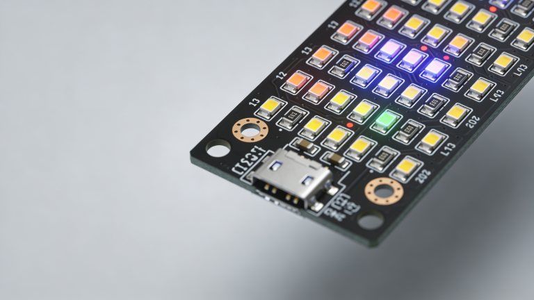
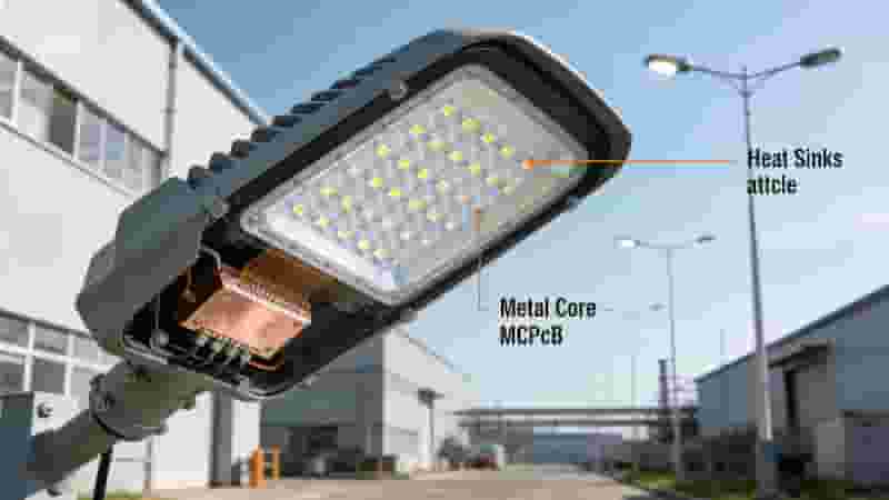
- LED Lighting: Street lights, automotive headlights, commercial panels, grow lights
- Automotive Electronics: Lighting modules, ECUs, EV components, charging systems
- Power Electronics: SMPS, motor drivers, inverters, DC-DC converters
- Industrial & Telecom: RF amplifiers, base stations, automation controls
Materials & Stack-Up Options
Aluminum vs Copper MCPCB
Aluminum MCPCB: Cost-effective, lightweight, ideal for general LED and power applications. Thermal conductivity 1.0–3.0 W/mK.
Copper MCPCB: Ultra-high thermal performance up to 8.0 W/mK, perfect for extreme high-power designs like RF amplifiers.
Dielectric Layers
| Dielectric Type | Thermal Conductivity | Applications |
|---|---|---|
| Standard | 1.0–1.5 W/mK | General LED lighting |
| High Thermal | 2.0–3.0 W/mK | High-power LED, automotive |
| Ultra-High Thermal | 3.0–8.0 W/mK | RF, extreme power density |
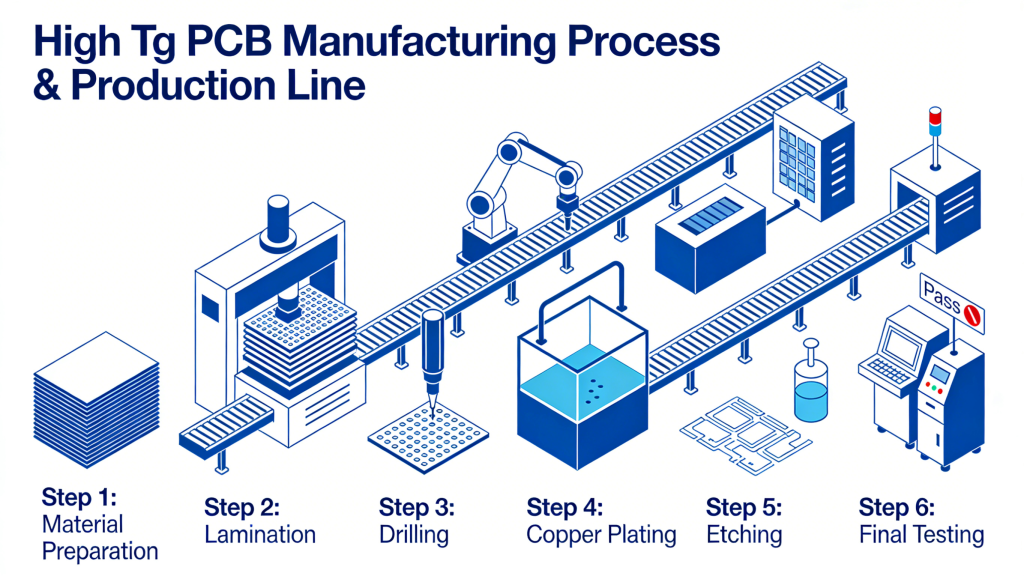
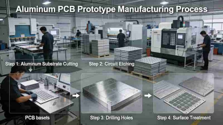
Production & Quality Control
Our MCPCB manufacturing follows strict processes to ensure thermal, electrical and mechanical reliability.
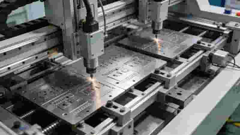
- Material preparation & precision cutting
- CNC drilling & via formation
- Circuit imaging & etching
- Plating for double/multilayer boards
- Solder mask & silkscreen application
- Surface finish treatment
- Routing, inspection & testing
Quality Control: 100% electrical test, AOI inspection, thermal performance verification, adhesion testing. Certifications: ISO 9001, RoHS, IPC-A-600.
MCPCB vs FR4 PCB
| Feature | Metal Core PCB (MCPCB) | FR4 PCB |
|---|---|---|
| Thermal Conductivity | 1.0–8.0 W/mK | 0.3–0.4 W/mK |
| Heat Dissipation | Excellent | Limited |
| Typical Use | High-power LED, automotive, power supply | Low-to-medium power electronics |
| Mechanical Strength | High | Moderate |
Why Choose Us as Your MCPCB Supplier
- Fast MCPCB prototyping (3–5 days) with low MOQ
- Competitive pricing for prototypes and mass production
- Expertise in aluminum & copper core design and production
- Free DFM review and professional engineering support
- Strict quality control and international certifications
- Global shipping and responsive customer service
Request Your MCPCB Quote
Get fast, professional Metal Core PCB (MCPCB) manufacturing service from China. We provide custom solutions, free DFM review and competitive pricing for global buyers.
- Send Gerber files for accurate quotation
- Free design and thermal optimization support
- Flexible MOQ from 1 piece for prototypes
- On-time delivery worldwide
Contact us now to start your MCPCB project!
Ultimate Guide to Multilayer PCB Layer Stackup & Thickness | Standard 4–14 Layer Configurations
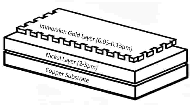
PCB Immersion Gold (ENIG) Surface Finish: Full Guide for Reliable Lead-Free PCBs
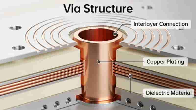
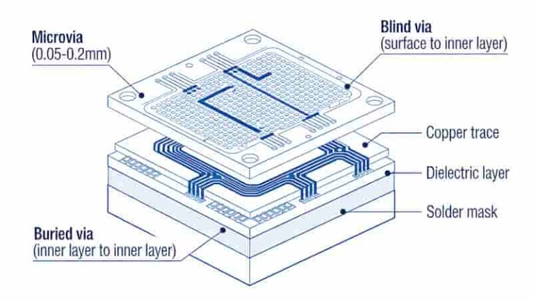
PCB Vias Explained: Through, Blind, and Buried Vias for Industrial PCB Design
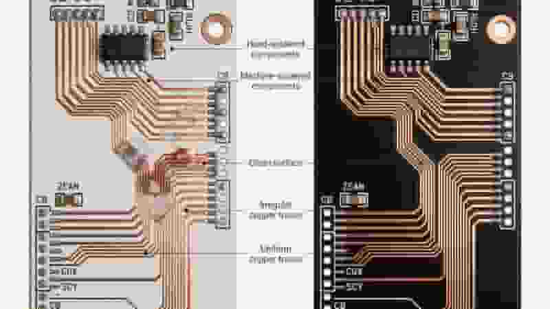
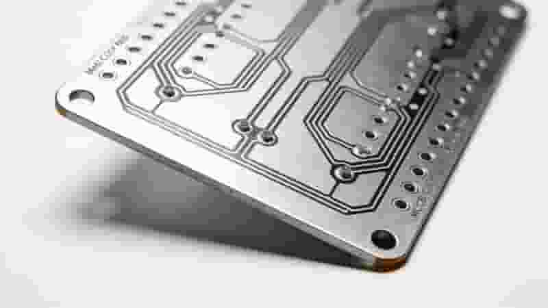
Key Differences Between Prototype and Production PCBs Explained
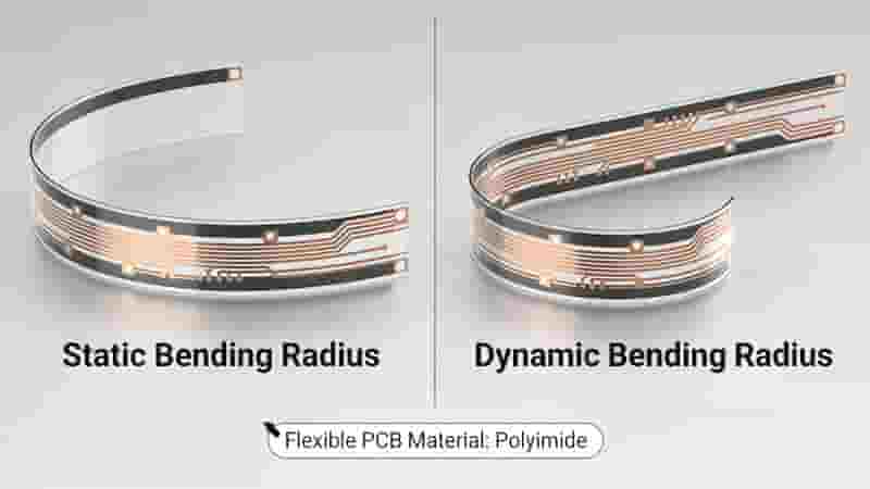
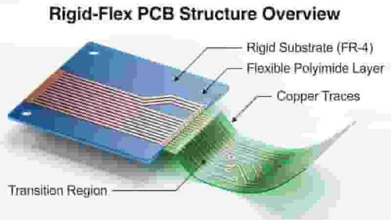
Single-Sided Flexible PCB Design Guide: Bending Radius, Trace Routing and Stiffeners