|

Understanding Plated Half-Holes (Castellated Holes) in PCB Design

Castellated Holes PCB Benefits - Advantages of Plated Half-Holes in Electronics

Plated Half-Holes (Castellated Holes) are critical edge interconnect structures in modern PCB design. They enable reliable module-to-board soldering, improve space efficiency, and enhance assembly accuracy for high-density electronic products.

What Are Plated Half-Holes (Castellated Holes)?

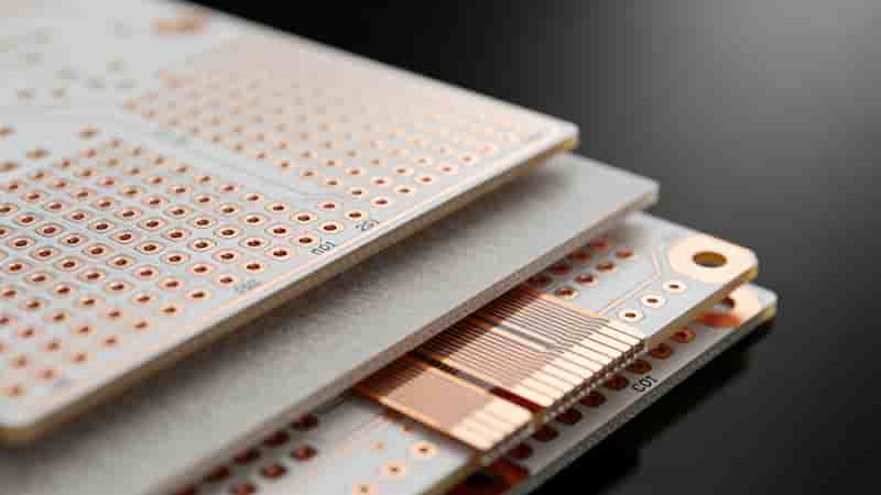
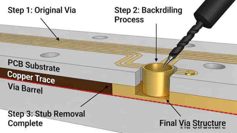
Plated Half-Holes (Castellated Holes) are semi-circular copper-plated holes located precisely at the edge of printed circuit boards. They act as edge connectors for PCB modules, allowing direct soldering to motherboards without additional connectors.
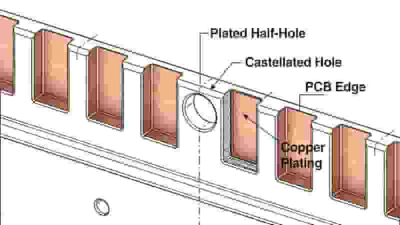
Plated Half-Holes PCB Structure - Castellated Holes for PCB Module Interconnection

Unlike standard through-holes, these structures expose only half of the plated barrel, creating ideal solderable surfaces for SMT assembly and modular PCB designs.

Structure & Working Principle

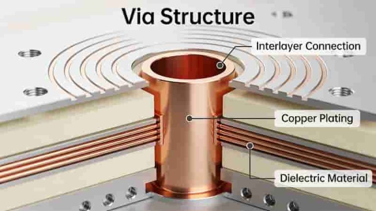
Plated Half-Holes (Castellated Holes) use the same plating technology as PTH (Plated Through Holes) but are placed at PCB edges. The copper plating covers the inner wall of the half-hole, forming stable electrical connections when soldered.
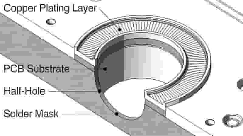
Cross Section of Plated Half-Hole - PCB Castellated Hole Internal Structure

These structures deliver excellent mechanical stability and electrical conductivity, making them ideal for compact electronics and modular PCB systems.

Critical PCB Design Guidelines

Follow these rules to ensure performance and manufacturability for Plated Half-Holes (Castellated Holes):

  • Position holes accurately at PCB edges with strict alignment
  • Define as plated through-holes in EDA design software
  • Provide clear drill files for PCB manufacturing
  • Add sufficient copper pads on all layers for stability
  • Comply with IPC standards for minimum size and spacing
  • Balance hole diameter with reliability and routing space
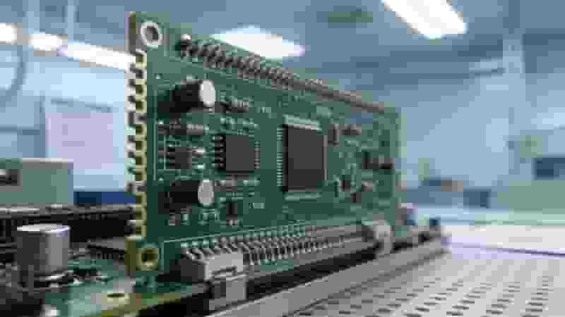
PCB Half-Hole Design Rules - Castellated Holes Layout Guidelines

Manufacturing Process

Modern production of Plated Half-Holes (Castellated Holes) uses precision processes to ensure high quality:

  1. Precision edge drilling with controlled depth
  2. Electroless copper plating and electroplating
  3. Laser routing for clean edge formation
  4. Surface finishing (ENIG, HASL, immersion silver)
  5. Automated optical inspection for quality control

Advanced processes eliminate burrs and ensure consistent plating quality for Plated Half-Holes (Castellated Holes) in mass production.

Key Advantages

  • Space Efficiency: Eliminates bulky connectors for miniaturized devices
  • High Reliability: Solder joints resist vibration and thermal cycling
  • Simplified Assembly: Fully compatible with standard SMT processes
  • Easy Inspection: Clear access for soldering and quality checking
  • Cost Effective: Reduces BOM cost and assembly complexity
  • Better Performance: Improved signal integrity for high-speed designs
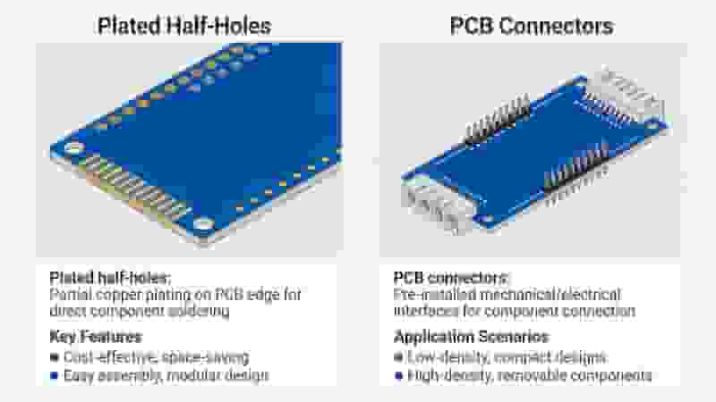
Castellated Holes PCB Benefits - Advantages of Plated Half-Holes in Electronics

Industrial Applications

Plated Half-Holes (Castellated Holes) are widely used across industries:

  • Modular PCB assemblies and compact electronic devices
  • High-density interconnect (HDI) PCB designs
  • Wearable electronics and IoT products
  • Automotive and industrial control modules
  • Rigid-flex PCB interconnection sections
  • Consumer electronics and communication equipment

Plated Half-Holes vs. Traditional Connectors

FeaturePlated Half-Holes (Castellated Holes)Traditional Connectors
Space UsageUltra-compact, edge-mountedRequires large mounting space
AssemblySMT compatible, single reflowSeparate assembly steps
ReliabilityHigh, solder joint connectionMedium, contact-based connection
CostLower BOM and assembly costHigher component cost

Conclusion

Plated Half-Holes (Castellated Holes) are essential in modern PCB design, delivering superior space efficiency, reliability, and cost savings. Following proper design and manufacturing best practices allows you to maximize the value of these structures in modular PCB projects.

Mastering the design rules, fabrication process, and applications of Plated Half-Holes (Castellated Holes) helps engineers build more reliable and competitive electronic products.

Need Reliable PCB Manufacturing & Assembly?

We specialize in high-quality Plated Half-Holes (Castellated Holes) PCB fabrication, prototyping, and full SMT assembly for global industrial clients. Get a free quote and DFM review today!

Request Free Quote
Contact Engineering Team
Multilayer PCB Layer Stackup and Thickness: Standard 4‑Layer to 14‑Layer Configurations

Posted on
0 Comments
Complete professional guide to multilayer PCB stackup design, standard thicknesses, layer arrangements, impedance control, and ready-to-use 4–14 layer configurations for industrial, high-speed, and high-reliability electronics. Why Multilayer PCB Stackup and Thickness Matter Today’s electronics demand smaller size, higher speed, greater integration, and longer reliability. Multilayer PCB stackup and total board thickness directly determine signal integrity,…
SMT PCB Assembly Line High Precision

Turnkey PCB Assembly Services | Full & Partial Solutions

Posted on
0 Comments
We provide end-to-end turnkey PCB assembly supporting full and partial models, with SMT assembly, THT, BGA/QFN, rigorous testing, and global logistics for industrial buyers, engineers, and importers. What Is Turnkey PCB Assembly Turnkey PCB assembly is a one-stop manufacturing solution covering PCB fabrication, component sourcing, assembly, testing, and delivery. We manage the full supply chain…
HDI PCB Microvia Types: Blind, Buried, Stacked Vias

HDI PCB Layout and Basic HDI Design Guidelines

Posted on
0 Comments
HDI PCB is an advanced printed circuit board technology for high‑component‑density electronics. This guide covers core HDI PCB layout principles, via design, trace rules, stackup, and IPC standards for engineers and buyers. What Is HDI PCB Layout? High Density Interconnects (HDI PCB) layout refers to advanced PCB design techniques used when trace widths drop below…
4 Types of PCB Open Circuit Diagram Repeated Gap Vacuum Scratched

PCB Open Circuit: Causes, Types, Diagnosis & Proven Solutions

Posted on
0 Comments
PCB open circuit is one of the most frequent defects in PCB manufacturing, causing production downtime, rework, delivery delays, and quality complaints. This professional guide explains definitions, types, root causes, inspection methods, prevention, and reliable fixes for global electronics buyers and engineers. What Is a PCB Open Circuit? A PCB open circuit is an interruption…
PCB Manufacturability Analysis Software Interface DFA Check

Design for Manufacturability and Assemblability of Printed Circuit Board

Posted on
0 Comments
Optimize your PCB design for high yield, low cost, and reliable assembly with industry-leading DFM and DFA principles aligned with IPC standards. What is Design for Manufacturing Design for Manufacturing, also known as concurrent or simultaneous engineering, focuses on the relationship between product physical design and manufacturing systems. By integrating DFM principles into product design,…
Plated Through Hole PTH Structure in PCB

What is the Difference Between PTH and Via in PCBs?

Posted on
0 Comments
Understanding the key differences between PTH and via is essential for optimizing PCB design and manufacturing. This article defines PTH and via, compares dimensions, functions, locations and finishing requirements. Typical applications and design considerations are also discussed. Defining PTH and Vias in PCBs PCBs serve as the foundation for almost all modern electronics. They provide…

FAQs About PCB Plated Half Hole / Castellated Hole Design & Fabrication

A: Edge-located semi-circular PTH with half copper-plated barrel, used for modular PCB directly soldering onto mainboard without extra connectors.

A: Save layout space, cut BOM expense, compatible with standard SMT reflow, stable anti-vibration solder joint and convenient post-solder inspection.

A: Place strictly on board outline edge, set as PTH in EDA, add full-layer pads and complete drill docs for manufacturer production.

A: Full-hole drilling + overall copper plating then edge routing cutting; high-precision batch adopts laser edge forming for smooth hole wall.

A: IoT modular sub-board, wearable device modules, automotive control unit, rigid-flex transition connection and compact HDI circuit.

A: Yes, edge exposed solder surface avoids hidden gap dust accumulation and improves assembly alignment precision compared to bottom hidden pads.

A: ENIG, Lead-free HASL and Immersion Silver are all applicable to guarantee good solderability of half-hole copper barrel.

A: Complete Gerber files, formal drill file and mechanical drawing marking all castellated hole exact positions on board edge.

Similar Posts