Summary: High Tg FR4 PCBs provide outstanding thermal stability, mechanical strength, electrical insulation, and cost efficiency for high-temperature electronics. This guide explains core properties, key benefits, industrial applications, and material comparisons to help engineers and purchasers select the right high Tg PCB solution for automotive, aerospace, industrial, and telecom systems.
What Is a High Tg PCB?
High Tg PCBs are rigid printed circuit boards designed to maintain stability at temperatures above 170°C. Tg stands for glass transition temperature — the point where substrate material changes from rigid to soft. Standard FR4 PCB Tg is 130–140°C, while high Tg FR4 PCB reaches 170°C, 180°C, or above 200°C for extreme environments.
For reliable performance, select a PCB material with Tg at least 20–25°C higher than your maximum operating temperature to avoid warping, delamination, or signal failure.
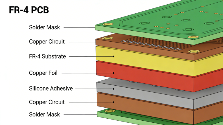
Why FR4 Is Preferred for High Tg PCBs
FR4 is the most widely used substrate for high Tg PCB due to its balanced performance, process compatibility, and cost advantage.
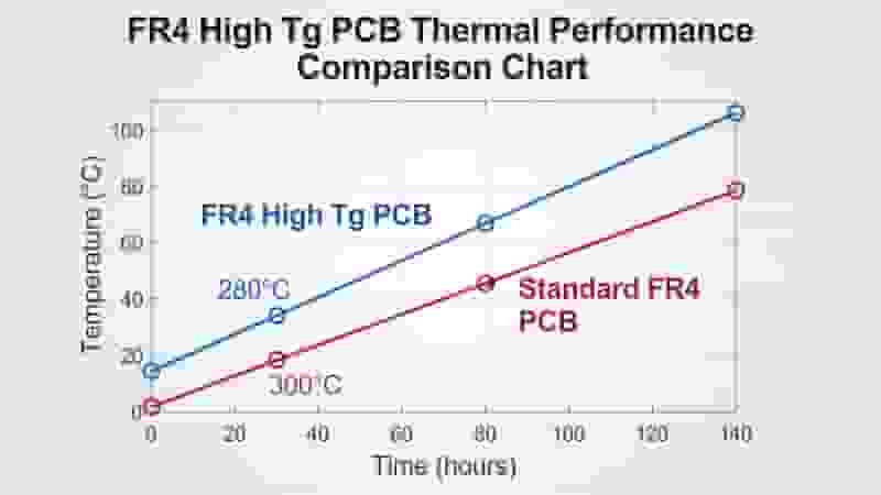
Excellent Thermal Stability
High Tg FR4 resists heat distortion above 170°C, maintaining rigidity and structural integrity during reflow, wave soldering, and long‑term high‑temperature operation. It prevents board warpage and extends service life.
Superior Electrical Performance
FR4 delivers stable dielectric properties, low signal loss, and strong insulation. These features preserve signal integrity for high‑speed circuits, power boards, and RF modules in telecom and industrial equipment.
Strong Mechanical Reliability
High Tg FR4 supports PTH, vias, and multilayer designs with excellent bonding strength. It resists impact, vibration, and thermal cycling — critical for automotive and aerospace applications.
Wide Process Compatibility
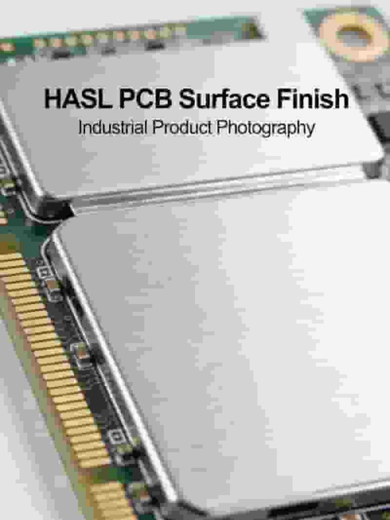
FR4 works with standard PCB manufacturing: plating, etching, solder mask, surface finishes (HASL, ENIG, immersion silver), and SMT assembly. It reduces production complexity and improves yield.
Cost-Effective Solution
Compared to polyimide, ceramic, or metal substrates, FR4 high Tg PCB offers professional performance at a lower cost, supporting mass production and prototype projects.
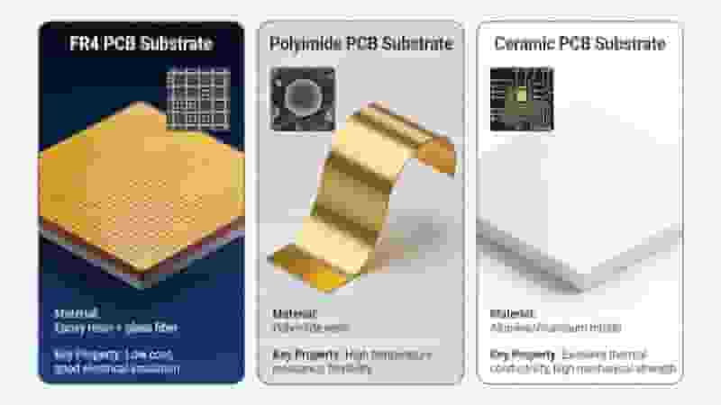
FR4 vs. Other High-Tg PCB Materials
| Material | Tg Range (°C) | Cost | Best For |
| High Tg FR4 | 170–200+ | Low–Medium | Automotive, industrial, telecom |
| Polyimide (PI) | 250–350+ | High | Extreme aerospace, military |
| Ceramic | 300+ | Very High | High‑power, high‑heat |
| Metal Core | N/A | Medium | LED, power devices |
For most industrial and automotive applications, FR4 high Tg PCB delivers the best balance of performance, reliability, and cost.
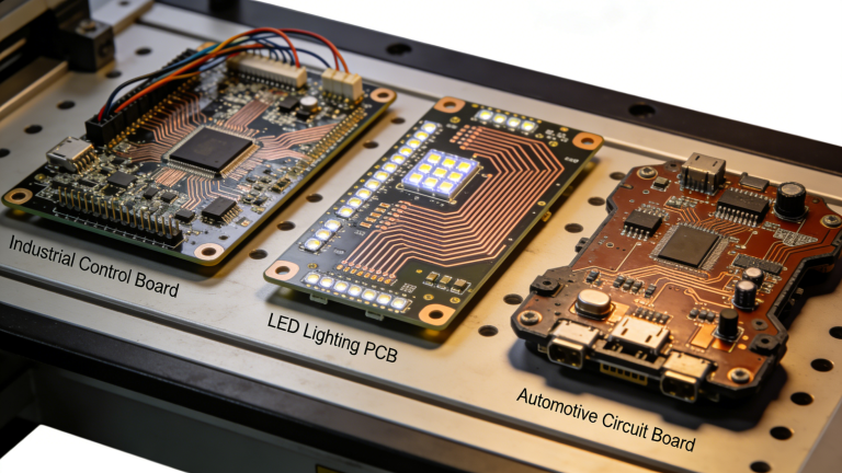
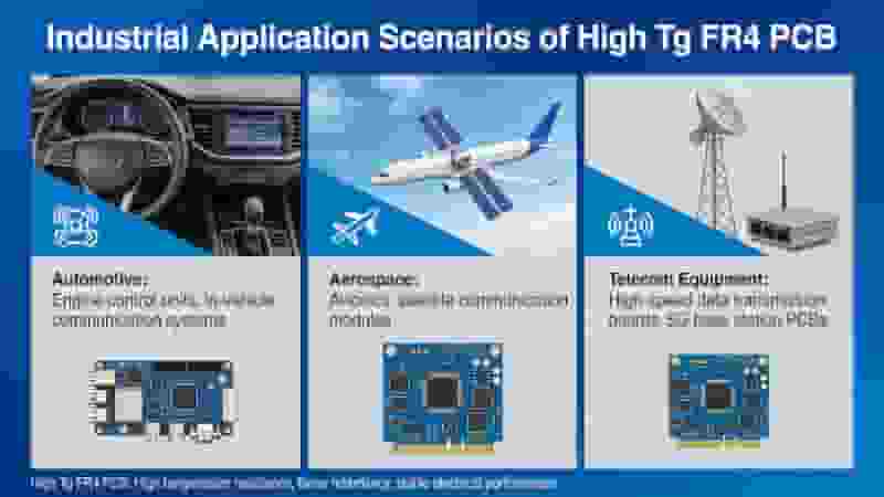
Key Applications of High Tg FR4 PCBs
- Automotive Electronics: Engine control units, sensors, automotive lighting, inverter boards
- Aerospace & Avionics: Satellite modules, navigation systems, flight control
- Industrial Equipment: IPC, power supplies, automation controllers
- Telecommunications: Base stations, routers, high‑speed data transmission
- Consumer & Industrial IoT: Power modules, smart devices, server boards
Conclusion
FR4 is the preferred material for high Tg PCBs because it combines excellent thermal resistance, electrical stability, mechanical strength, and manufacturing compatibility at a competitive cost. It meets the demands of high‑temperature environments in automotive, aerospace, industrial, and telecom applications.
Choosing high Tg FR4 PCB ensures long‑term reliability, stable performance, and optimized total cost for your electronic systems.
Get Your Custom High Tg FR4 PCB Solution
Need reliable high Tg FR4 PCBs for your project? Contact us for DFM analysis, personalized quotes, and professional manufacturing support.
Inquire Now | Get a Free Quote
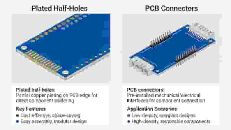
Understanding Plated Half-Holes (Castellated Holes) in PCB Design
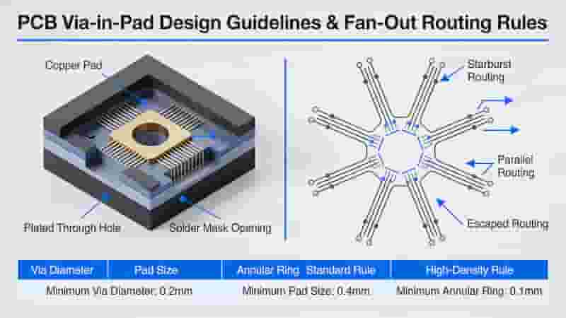
Via-In-Pad Design Guidelines and Manufacturing Process for PCB
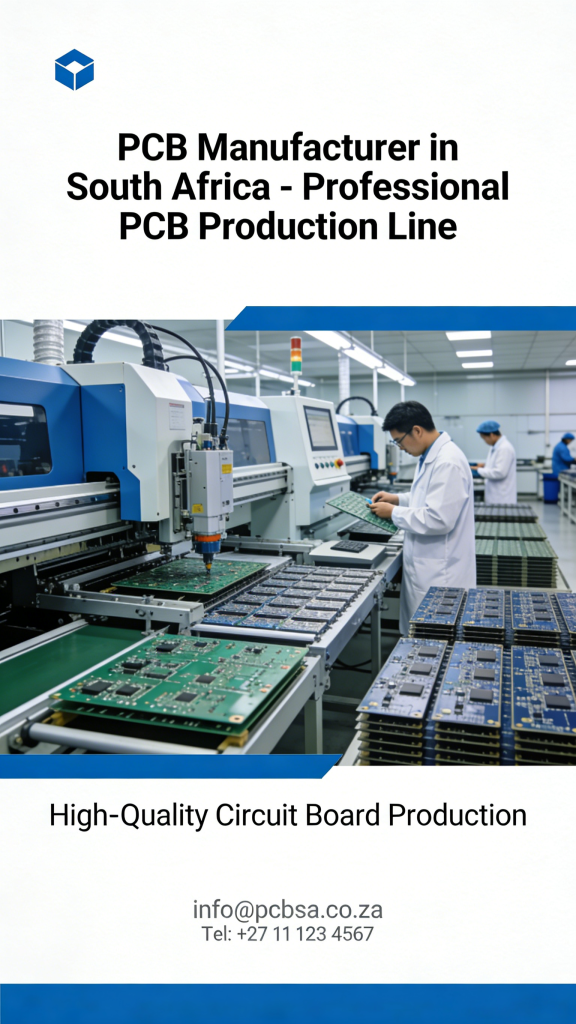
PCB Manufacturer in South Africa | Reliable Custom PCB & PCBA Services
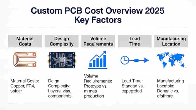
Key Factors Influencing Custom PCB Costs in 2025
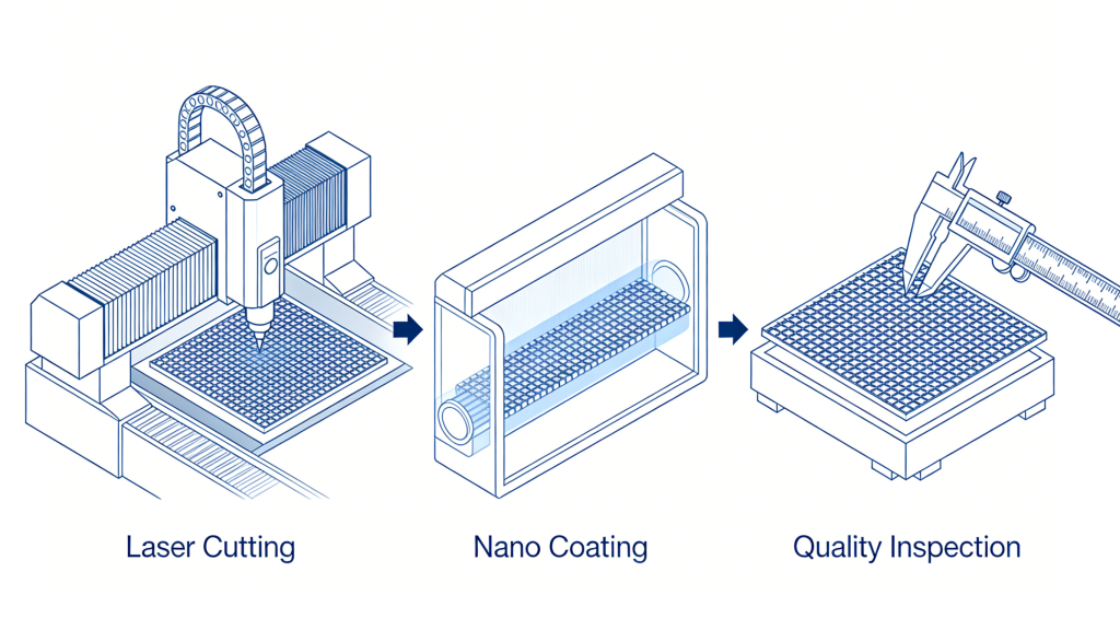
Nano-Coated PCB Stencil Manufacturing for Precision & Durability