High Tg PCB materials are essential for circuits that operate in extreme heat. This guide covers what High Tg means, its advantages over standard PCBs, common materials, real-world applications, and tips for selecting the best option. Whether you’re designing for electronics in harsh conditions or seeking reliable PCB assembly services, we have you covered with our expertise in high-performance PCB manufacturing.
What Are High Tg PCB Materials?
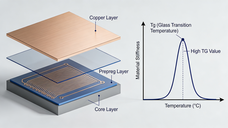
In the realm of PCB manufacturing, High Tg PCB materials are engineered to withstand elevated temperatures without compromising structural integrity or electrical performance. The term “Tg” refers to the Glass Transition Temperature, the point at which a PCB substrate transitions from a rigid to a softened state, typically measured in degrees Celsius (°C).
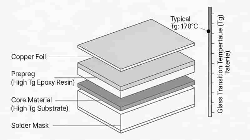
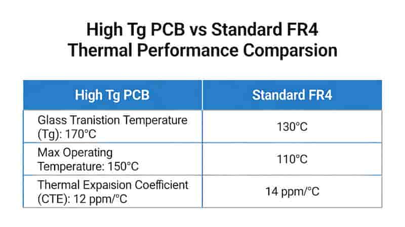
Standard FR4 materials have a Tg of approximately 130–140°C, while High Tg PCBs, with a Tg of 170°C or higher, offer superior thermal stability for demanding applications. For instance, in high-temperature environments like automotive engine control units or industrial power modules, standard PCBs risk delamination or warpage, leading to circuit failure.
High Tg materials mitigate these risks by maintaining mechanical strength and dimensional stability under thermal stress. We specialize in High Tg PCB fabrication and assembly, ensuring reliability for industries such as aerospace, automotive, and consumer electronics.
Advantages and Benefits of High Tg PCB Materials
High Tg PCB materials, with a glass transition temperature (Tg) of 170°C or higher, deliver superior performance in high-temperature environments compared to standard FR4 PCBs (Tg ≈ 130–140°C). We leverage these materials to ensure reliability for demanding applications.
Enhanced Thermal Stability
High Tg materials maintain structural integrity at elevated temperatures, resisting softening or deformation. This is critical for applications like automotive engine control units, where temperatures often exceed 150°C.
Reduced Coefficient of Thermal Expansion (CTE)
High Tg PCB substrates exhibit lower CTE, minimizing dimensional changes during thermal cycling. For multilayer PCBs, this reduces stress on vias and solder joints, preventing cracks.
Improved Mechanical Strength
High Tg PCBs offer superior mechanical durability, resisting warpage and bending under heat. This is vital for dense assemblies in industrial power modules.
Enhanced Electrical Performance
With better dielectric stability at high temperatures, High Tg PCB materials support consistent signal integrity, crucial for high-frequency applications like aerospace radar systems.
| Property | Standard FR4 (Tg: 130–140°C) | High Tg FR4 (Tg: 170–180°C) |
|---|---|---|
| Thermal Stability | Limited above 130°C | Stable up to 170°C+ |
| CTE (ppm/°C) | ~14–18 | ~10–14 |
| Moisture Absorption | Moderate | Low |
| Typical Applications | Consumer electronics | Automotive, aerospace |
Common Types of High Tg PCB Materials
High Tg PCB materials, characterized by a glass transition temperature (Tg) of 170°C or higher, are tailored for applications requiring robust thermal and mechanical performance. We leverage a range of High Tg materials to meet diverse industry needs.
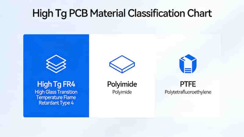
High Tg FR4
High Tg FR4, an enhanced version of standard FR4, offers a Tg of 170–180°C, making it a cost-effective choice for automotive electronics and industrial controls. We frequently use High Tg FR4 for high Tg multilayer PCB designs.
Polyimide
Polyimide substrates, with a Tg exceeding 200°C, excel in extreme environments, such as aerospace avionics and military electronics. They provide superior chemical resistance and flexibility for flex or rigid-flex PCBs.
PTFE-Based Materials (e.g., Rogers)
PTFE-based substrates combine High Tg (often >200°C) with excellent dielectric properties, ideal for 5G antennas and radar systems. Their low dielectric loss enhances signal integrity for high-frequency designs.
| Material Type | Tg Range (°C) | Key Features | Applications | Cost Level |
|---|---|---|---|---|
| High Tg FR4 | 170–180 | Cost-effective, low CTE | Automotive, industrial | Moderate |
| Polyimide | 200–250 | High thermal resistance | Aerospace, military | High |
| PTFE (Rogers) | 200+ | Low dielectric loss | 5G, radar, RF | Very High |
Applications of High Tg PCBs Across Industries
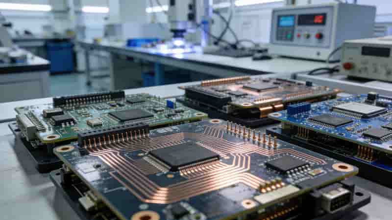
High Tg PCB materials are critical for electronics operating in extreme thermal environments. We deliver reliable High Tg PCB solutions for global industrial clients across key sectors.
Automotive Electronics
In automotive applications, High Tg PCBs ensure reliability under high temperatures and vibrations. Engine control units (ECUs) and battery management systems (BMS) often operate near 150°C.
Aerospace and Defense
Aerospace electronics demand materials that withstand extreme temperatures and radiation. Polyimide-based High Tg PCBs provide superior chemical resistance and durability.
Industrial Equipment
High Tg PCBs are vital for industrial applications like variable frequency drives and welding machines, where thermal cycling is common.
Consumer Electronics
In high-power consumer devices, High Tg PCB materials prevent thermal degradation and ensure stable performance in humid environments.
How to Choose the Right High Tg PCB Material
Selecting the appropriate High Tg PCB material is critical to ensuring reliability in high-temperature applications. We provide expert guidance to help engineers make informed decisions.
- Step 1: Assess operating temperature and environmental conditions
- Step 2: Verify Tg and Td values against IPC standards
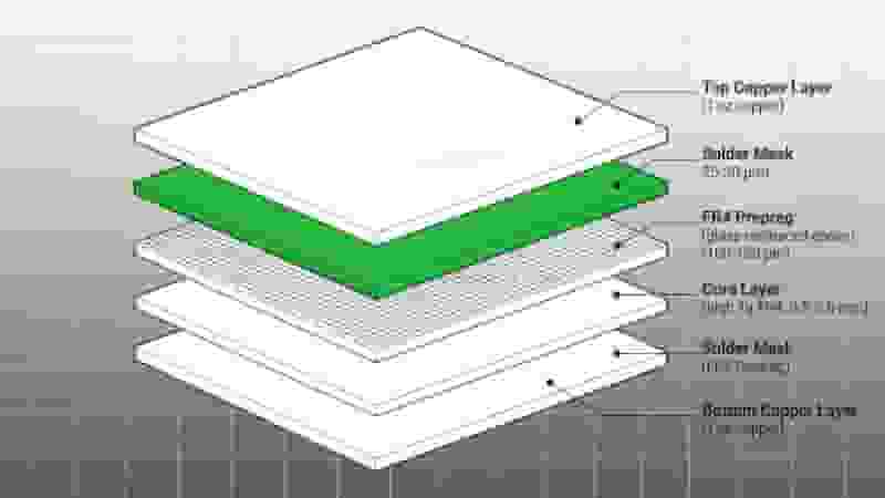
- Step 3: Consider layer count, thickness and multilayer design needs
- Step 4: Balance performance requirements with project budget
- Step 5: Avoid CTE mismatch and material selection pitfalls
Manufacturing Process and Considerations for High Tg PCBs
The manufacturing of High Tg PCBs requires specialized processes to ensure thermal stability and reliability. We employ advanced equipment and stringent quality controls to produce high-quality High Tg PCB products.
- Precision lamination with controlled temperature and pressure
- High-speed laser drilling for accurate via formation
- Optimized SMT reflow profiling to prevent board warpage
- Full testing including DSC, TMA and electrical verification
Surface Mount Technology (SMT) Compatibility
High Tg PCBs are well-suited for SMT assembly, as they withstand reflow soldering temperatures (up to 260°C). However, careful thermal profiling is essential to avoid board warpage. advanced reflow ovens and real-time monitoring ensure compatibility with complex assemblies.
High Tg PCBs vs. Other High-Temperature Solutions
High Tg PCBs are a cornerstone for high-temperature electronics, but ceramic PCBs and metal-core PCBs (MCPCBs) also address thermal challenges. We help clients choose the optimal substrate for their needs.
| Substrate Type | Tg Range (°C) | Thermal Conductivity | Cost | Applications |
|---|---|---|---|---|
| High Tg PCB | 170–250 | 0.3–0.5 W/m·K | Moderate | Automotive, aerospace |
| Ceramic PCB | 300+ | 20–200 W/m·K | High | High-power RF |
| MCPCB | <130 | 1–10 W/m·K | Low | LED, power electronics |
Need Reliable High Tg PCB Solutions?
We provide professional High Tg PCB manufacturing, assembly and customization for global industrial buyers. Get free DFM review, quick quote and tailored support for your high-temperature projects.
Request a Quote
Contact Us
Why FR4 Is the Preferred Material for High Tg PCBs: Benefits and Applications
10 Essential Tips for Optimizing PCB Design for Manufacturing
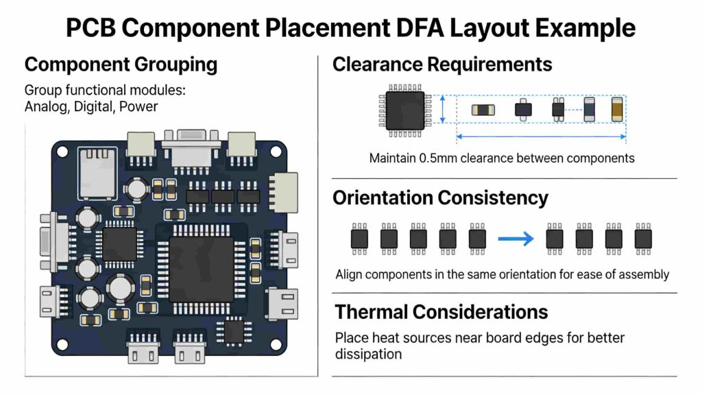
PCB DFM and DFA: Best Practices for Optimal Design
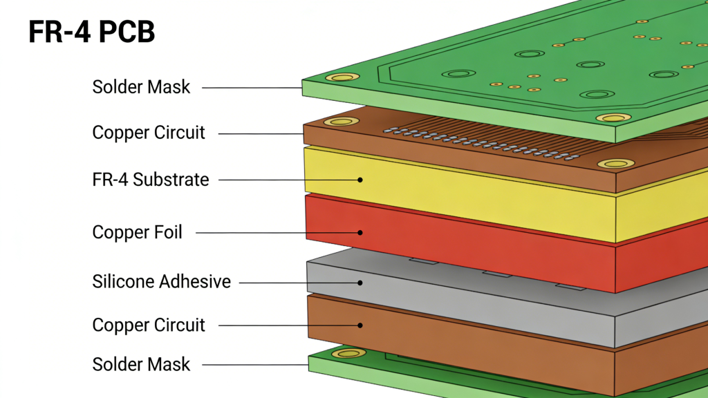
What is FR-4 Material in PCB Fabrication? Complete Engineering Guide
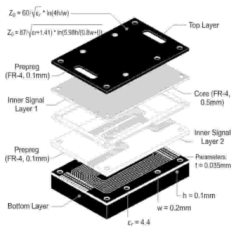
PCB Stackup Design Guidelines: Best Practices for 2, 4, 6 Layers