Via-In-Pad Design Guidelines and Manufacturing Process for PCB
Via-in-pad (VIP) is a critical PCB design technique where vias are drilled directly on SMD and BGA pads to support high-density interconnects. This guide covers via-in-pad fundamentals, design rules, manufacturing processes, and comparisons between VIP and non-VIP processes to ensure reliable PCB assembly and performance.
What Is Via-In-Pad?
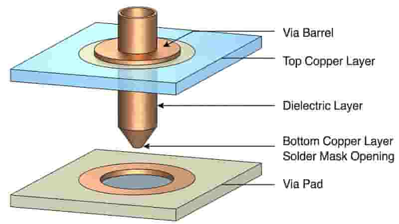
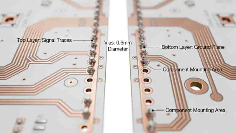
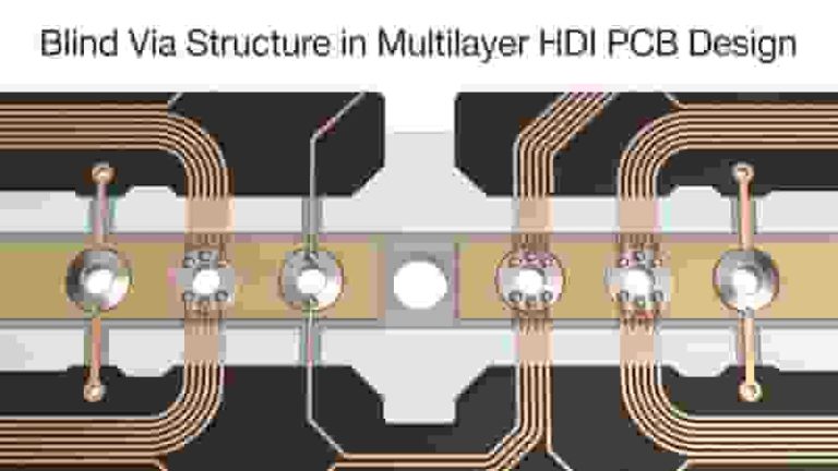
Via-in-pad (VIP) means drilling vias directly on component pads, typically SMD pads (0603 or larger) and BGA pads. Vias on through-hole component pads are not classified as via-in-pad because they are used for component lead insertion and soldering.
As electronics become lighter, thinner, and smaller, PCBs require higher density and more complex routing. Smaller BGA packages with finer pin pitch reduce available routing space, making via-in-pad essential for layer transitions in compact designs.
When to Use Via-In-Pad
Via-in-pad is required in two main high-density PCB scenarios:
BGA pin pitch is too small for traditional fan-out routing
Bypass capacitors on the back of dense BGA components have no safe routing space for external vias
We recommend avoiding via-in-pad when routing space permits, as it increases PCB manufacturing cost and lead time.
Via-In-Pad Design Guidelines
When Via-In-Pad Is Not Needed
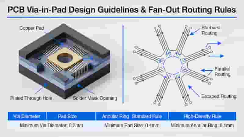
Complete fan-out routing before layer wiring. For high-pin-count BGAs, place vias centered between pads. Standard BGA fan-out parameters:
Via diameter: 0.15-0.2 mm
Trace width: 3-4 mil
Annular ring: 0.3-0.4 mm
Minimum fan-out-compatible BGA pitch: 0.35 mm
When Via-In-Pad Is Necessary
Verify via hole size before BGA fan-out. Use via-in-pad when pin pitch is too small for fan-out, and route BGA pins through inner layers or the component side.
Via-In-Pad Manufacturing Process
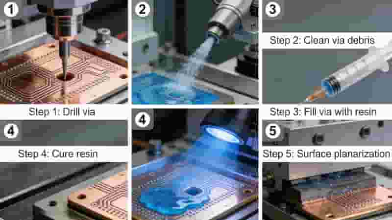
BGA pad vias are standard via-in-pad structures and must be plugged and plated for reliable soldering unless customer specifies otherwise. For customer-requested fully plugged vias, all SMD pad vias are treated as via-in-pad.
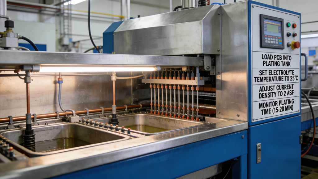
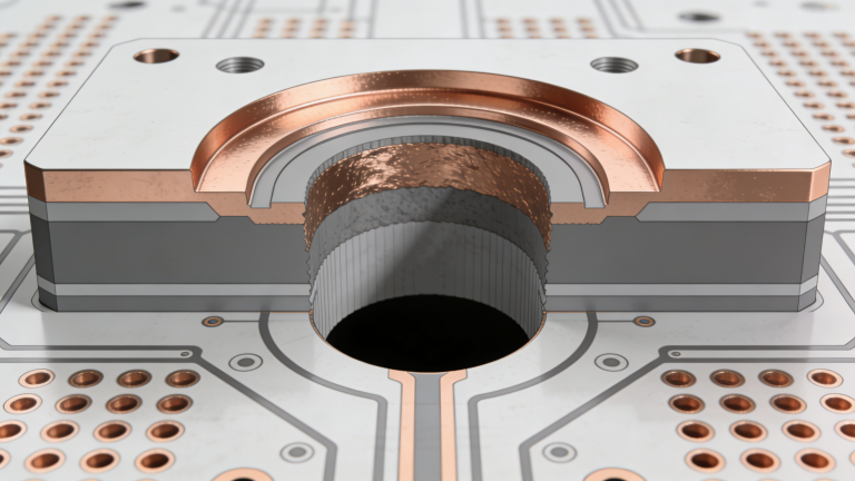
The typical resin-filled via-in-pad process ensures flat pad surfaces and stable SMT assembly.
VIP vs. Non-VIP Process Comparison
Item
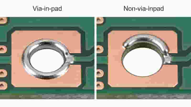
With Via-In-Pad Process
Without Via-In-Pad Process
Pad Condition
Plugged, plated, planarized
Open via, uneven surface
Solder Quality
Strong joints, no voids
Weak joints, solder wicking
Assembly Risk
Low, stable for BGA/SMD
High, solder balls and defects
Cost & Lead Time
Higher, longer cycle
Lower, faster production
DFM Checks for Via-In-Pad
Our automated DFM analysis quickly detects via-in-pad in design files and provides engineer-friendly modification suggestions to reduce cost. We also notify production teams that via plugging is required for via-in-pad boards.
DFM checks help identify quality risks early, cut iterations, lower cost, and improve product reliability for global PCB buyers.
Conclusion
Via-in-pad is an essential technique for high-density PCB design, especially for fine-pitch BGA and compact SMD circuits. Following proper design guidelines and manufacturing processes ensures reliable performance, while DFM checks optimize cost and yield.
We specialize in via-in-pad PCB manufacturing and assembly for industrial, telecom, and high-tech applications worldwide.
Need Professional Via-In-Pad PCB Solutions?
Contact us for PCB design, DFM analysis, manufacturing, and assembly quotes.
We provide professional PCB components purchasing services with original factory supply, transparent pricing, full traceability, and flexible solutions for engineers, buyers, and manufacturers worldwide. Core Advantages of Our Components Purchasing Services 100% Original ProductsWe only source from original factories and authorized agents to guarantee authentic PCB components and consistent quality. Reasonable & Transparent PricingOur pricing…
Double sided PCB assembly supports high‑density circuit design by mounting components on both top and bottom sides of the board. This professional guide explains core definitions, full manufacturing processes, soldering technologies, pros and cons, design best practices, quality control, and application scenarios to help industrial buyers, engineers and procurement teams make informed decisions. What Is…
This professional guide compares Aluminum PCBs and FR4 PCBs in thermal performance, electrical properties, mechanical strength, cost, and ideal applications to help engineers and purchasers select the right PCB for reliable export projects. What is FR4 PCB FR4 PCB is the most widely used rigid PCB material, made of woven fiberglass cloth bonded with flame‑resistant…
Via-in-Pad technology places vias directly within surface mount pads to save space, improve routing efficiency, and enhance PCB density for HDI and high-speed designs. What Is Via-in-Pad Technology for PCBs? Before understanding via-in-pad, let’s review common PCB via types: Plated-through holes (PTHs) span the entire board, blind/buried vias connect partial layers, and microvias (~0.1mm) link…
PCB soldering is the foundation of reliable electronics assembly. This professional guide covers proven methods for how to solder on PCB, including hand soldering, wave soldering, reflow soldering, and selective soldering, with industrial best practices to eliminate defects and ensure long-term performance for industrial, automotive, and aerospace applications. What is PCB Soldering? A Foundation for…
In today’s competitive electronics manufacturing landscape, understanding PCB assembly cost is critical for engineering and procurement teams. This guide breaks down all pricing factors, assembly types, volume impacts, and practical strategies to optimize your budget without sacrificing quality. What Is PCB Assembly? PCB assembly (PCBA) is the process of mounting electronic components onto a bare…
Copper core PCBs are advanced metal-core printed circuit boards engineered for superior thermal management, making them the ideal choice for high-power LED systems and industrial power electronics. With exceptional thermal conductivity, mechanical stability, and long‑term reliability, copper‑based PCBs outperform standard aluminum PCBs and FR4 boards in demanding thermal environments. What Is a Copper Core PCB…
In today’s fast‑paced product development cycles, rapid PCB prototyping and accelerated production services are critical for first‑mover advantage. This guide covers quick‑turn turnaround times, fast PCB manufacturing lead times, and how express PCB solutions support agile hardware design and faster time‑to‑market. Why Rapid PCB Prototyping and Production Matter In today’s fast‑paced product development world, time…
We provide end-to-end turnkey PCB assembly supporting full and partial models, with SMT assembly, THT, BGA/QFN, rigorous testing, and global logistics for industrial buyers, engineers, and importers. What Is Turnkey PCB Assembly Turnkey PCB assembly is a one-stop manufacturing solution covering PCB fabrication, component sourcing, assembly, testing, and delivery. We manage the full supply chain…
Automotive printed circuit boards are critical building blocks for modern vehicles, supporting engine control, infotainment, safety systems, ADAS, and electric powertrains. These boards deliver stable performance under extreme temperatures, vibration, humidity, and EMI while meeting strict automotive quality standards. What Are Automotive PCBs? Automotive printed circuit boards are specially designed and manufactured for vehicle electronic…
Soldering is the process of joining metal components using melted solder, which has a lower melting point than base metals. It is the core connection technology in the electronics industry and the most important step in PCB assembly. PCB soldering refers to the process of fixing electronic parts onto a printed circuit board. It is…
Plated Through Holes (PTH) are essential conductive structures in printed circuit boards that ensure stable interlayer connections, reliable component mounting, and long‑term performance. This guide explains PTH basics, design rules, manufacturing, comparisons to NPTH, blind vias, buried vias, and best practices for industrial PCB applications. What Are Plated Through Holes (PTH) Plated Through Holes (PTH)…
We specialize in LED PCB manufacturing and assembly with aluminum, copper & flexible substrates featuring superior heat dissipation. ISO 9001 certified, fast turnaround & competitive pricing for global LED lighting projects. Superior Heat Dissipation 1-9 W/mK thermal conductivity Fast Turnaround 24-hour quote, 3-5 days delivery ISO 9001 Certified International quality standard One-Stop PCBA Service From…
A flexible PCB (FPC) is a thin, bendable printed circuit that can fold, twist, and fit compact 3D spaces. This guide covers structure, materials, stack‑ups, design rules, manufacturing, and real‑world use cases to help global engineers and buyers select the right flex solution. Introduction In every new generation of electronic products, there is a clear…
We provide professional Double Sided PCB manufacturer in China for global industrial buyers, engineers, and procurement teams. Our full capabilities cover prototyping, mass production, DFM, assembly, and strict quality control to meet IPC standards for reliable, high-performance double-layer PCBs. Why Choose Us for Double Sided PCB Manufacturing We are a professional manufacturer focused on Double…
Selecting a trusted PCB prototype manufacturer directly impacts product performance, development speed, and long-term reliability. This professional guide helps engineers and buyers evaluate technical capabilities, quality systems, lead times, and services to pick the ideal partner for your electronic projects. Technical & Manufacturing Capabilities A professional PCB prototype manufacturer must match your design complexity and…
Get reliable quick turn PCB assembly with one-stop PCB fabrication, components sourcing, SMT/THT assembly and testing, helping you turn ideas into working boards in days instead of weeks. What Is Quick Turn PCB Assembly Service? Quick turn PCB assembly is an accelerated manufacturing process that integrates PCB fabrication, component sourcing, SMT/THT assembly and testing to…
Discover what drives custom PCB costs in 2025, from material choices and layer counts to board size and production volume. Compare area-based pricing for prototypes with detailed cost calculations for bulk orders. Unlock cost-saving strategies to balance quality and budget for your industrial & electronics projects. Introduction In 2025, custom PCBs continue to be the…
As a trusted low-cost PCB assembly service provider, we deliver high-quality, affordable PCB assembly for prototypes, low-volume and mass production, with no hidden costs and global shipping. Why Low-Cost PCB Assembly Is Essential Printed circuit boards are the backbone of modern electronics, connecting components to deliver functional devices. With growing demand, more PCB assembly service…
Learn what prototype PCB assembly is, why it matters, types, process steps, cost factors, and how to choose a reliable partner. We provide fast‑turn, high‑quality prototype PCB assembly for global customers. Prototype PCB Assembly Guide: Process, Types, Cost & Partner Selection A printed circuit board prototype refers to the initial version of a printed circuit…
Step stencils optimize solder paste deposition for mixed-component PCBs, improving yield, reliability, and first-pass success in SMT assembly for electronics, automotive, and medical devices. Imagine a production line where tiny 01005 components sit alongside large edge connectors on a single printed circuit board. The challenge? Applying just the right amount of solder paste to each…
Learn professional flex PCB soldering techniques, temperature control, defect prevention, and step-by-step processes to ensure reliable, long-lasting assemblies for industrial and electronic applications. Why Flex PCB Soldering Is Different From Rigid PCBs Flex PCBs use thin polyimide substrates that are highly sensitive to heat and mechanical stress. While basic solder principles match rigid boards, flex…
Expedited PCB services deliver fast circuit board prototyping, manufacturing, and assembly for global engineers and procurement teams. We provide high‑quality rush PCB solutions with reliable lead times, strict quality control, and competitive pricing for urgent export orders. Why Choose Expedited PCB Services In the global electronics industry, speed directly impacts time‑to‑market and project success. Expedited…
We are a trusted Aluminum PCB manufacturer and MCPCB supplier in China, delivering fast prototypes and small‑to‑medium volume production for LED lighting, power supplies, and high‑power electronics. Our in‑house lines ensure stable quality, controlled costs, and on‑time delivery for global buyers. Aluminum PCB Manufacturing Capabilities With 15+ years of expertise in Aluminum PCB and MCPCB…
Reliable aluminum PCB manufacturer & MCPCB supplier in China, providing fast prototypes and small to medium-volume production for LED lighting, power supply and other high-power electronics. About Our Aluminum PCB Services We specialize in aluminum PCB and metal core PCB fabrication, from single-sided aluminum PCBs for LED lamps to complex multilayer aluminum boards for power…
FAQs About Via-In-Pad (VIP) PCB Design & Manufacturing
A: Via-In-Pad means drilling vias directly on SMD and BGA pads. It is a key design method for high-density and compact PCB layouts.
A: Use VIP when fine-pitch BGA leaves no space for traditional fan-out routing or bypass capacitors lack room for external vias.
A: Via-in-pad requires extra plugging and plating processes, which raise production cost and extend lead time.
A: Via diameter 0.15–0.2 mm, trace width 3–4 mil, annular ring 0.3–0.4 mm, minimum compatible BGA pitch 0.35 mm.
A: VIP vias need resin filling, plugging and planarization to keep pads flat and ensure reliable SMT soldering.
A: VIP delivers flat pads, stable solder joints and low assembly risks, but costs more and takes longer production time.
A: Open vias may cause solder wicking, solder balls, voids and poor solder joints during assembly.
A: DFM identifies VIP structures early, reminds production to do via plugging, gives optimization tips and reduces cost and quality risks.
PCB stackup design directly determines signal integrity, EMI control, power stability and manufacturing reliability. This guideline provides professional, field-proven best practices for 2‑layer PCB stackup, 4‑layer PCB stackup and 6‑layer PCB stackup for industrial electronics, communications equipment and high‑speed digital products. Introduction to PCB Stackup Design PCB stackup design is the foundation of high‑performance printed…
Advanced controlled impedance PCB manufacturing for high-speed, RF and telecom designs, delivering precise 50 Ω / 90-100 Ω impedance, tight tolerances and fast global turnaround. Tight-tolerance controlled impedance: 50 Ω single-ended and 90/100 Ω differential traces engineered for consistent signal integrity. Multilayer stackups with FR-4 and high-frequency materials (Rogers, hybrid) for complex high-speed designs. Full…
Blind vias and buried vias are core structures for high‑density interconnect (HDI) and high‑speed PCBs. They boost routing density, signal integrity, and miniaturization while optimizing layer stackups. This guide covers definitions, differences, design rules, manufacturing, and industrial applications for global engineers and buyers. Introduction As printed circuit boards become more compact and integrated, advanced via…
This guide covers core PCB pad design principles, component spacing, IPC standards, SMD/through-hole rules, thermal management, and DFM to boost assembly yield, reliability, and performance for industrial and export-grade PCBs. PCB Component Layout & Spacing Rules When laying out PCB components, designers must balance minimum component spacing against component height and thickness. Proper spacing prevents…
Learn what tented vias are, how they work, key benefits, IPC standards, design rules, and best applications for high‑performance PCB manufacturing and assembly. What Is a Tented Via in PCBs? A tented via is a plated through‑hole (PTH), blind via, or buried via fully or partially covered with solder mask on one or both sides…
Plated half-holes, also called castellated holes, provide a space-efficient way to interconnect separate PCB modules by soldering. Unlike bottom pads, their edge positioning simplifies mounting and enhances reliability. This article explains everything about plated half-hole structures, design guidelines, manufacture, benefits and use cases. Structure of Plated Half-Holes Plated half-holes, also known as castellated holes, resemble…